Ford F150 Pickup. Instruction - part 1536


  Index      Ford     Ford F150 Pickup - service and repair instruction 2003 year


Search            copyright infringement  


Content   ..  1534  1535  1536  1537   ..


Ford F150 Pickup. Instruction - part 1536


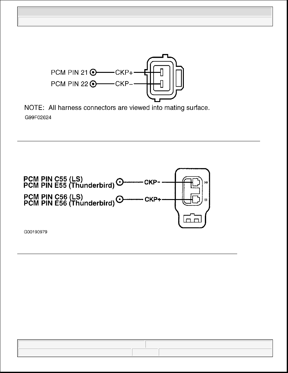
Fig. 290: Identifying CKP Sensor Circuits & Connector Terminals (Focus 2.3L, Ranger 2.3L & ZX2) 
Courtesy of FORD MOTOR CO. 

Fig. 291: Identifying CKP Sensor Circuits & Connector Terminals (LS V8 & Thunderbird) 
Courtesy of FORD MOTOR CO. 


2003 Ford Pickup F150 

2003 ENGINE PERFORMANCE Self-Diagnostics - CNG, Flex-Fuel & Gasoline


Fig. 292: Identifying CKP Sensor Circuits & Connector Terminals (All Others) 
Courtesy of FORD MOTOR CO 

Testing 

1) Check CKP Signal Sent To PCM 
 
Connect scan tool to Data Link Connector (DLC). Turn ignition switch to ON position. Select RPM PID. 
Disable inertia switch and crank engine or crank engine at WOT (make certain engine will not start). Is 
engine RPM displayed on scan tool while cranking? If yes, CKP, PCM and harness working properly. 
Concern is elsewhere. See TROUBLE SHOOTING - NO CODES - CNG, FLEX-FUEL & 
GASOLINE
 article. If no, go to next step. 

2) Check Timing Cover, CKP Sensor & External Trigger Wheel (Outside Timing Cover) For 
Obvious Physical Damage 
 
Turn ignition switch to OFF position. Visually inspect the timing cover, CKP sensor and external trigger 
wheel for obvious physical damage. Do any parts appear physically damaged? If yes, repair or replace 
damaged parts. If no, go to next step. 

3) Check For Proper CKP Bias Voltages In PCM 
 
Disconnect CKP sensor. Turn ignition switch to ON position. Measure voltages of CKP(+) and CKP (-) 
circuits individually between the CKP harness connector and battery negative terminal. See Fig. 287-Fig. 
292
 . Is each measurement 1.0-2.0 volts? If yes, go to next step. If no, go to step 8). 

4) Check CKP Sensor Resistance 
Measure CKP sensor resistance between the (+) and (-) terminals. Is resistance 250-1000 ohms? If yes, go 
to next step. If no, replace CKP sensor and perform 

PCM RESET PROCEDURE

 under CLEARING 

CODES under SELF-DIAGNOSTIC SYSTEM. 

NOTE:

CKP sensor resistance values change significantly with temperature rise.


2003 Ford Pickup F150 

2003 ENGINE PERFORMANCE Self-Diagnostics - CNG, Flex-Fuel & Gasoline


5) Check CKP Circuit Harness Shield Ground 
Measure the resistance between the CKP harness shield and battery negative terminal. Measure at the 
closest possible location to the CKP sensor. Is resistance less than 5 ohms? If yes, go to next step. If no, 
repair open circuit or poor ground connection. 

6) Check For Short Between CKP(+) & CKP(-) In Harness 
Turn ignition switch to OFF position. Disconnect PCM. Measure resistance across the CKP(+) and CKP(-
) pins at the CKP harness connector. Is resistance less than 10 k/ohms? If yes, REPAIR short circuit. If 
no, go to next step. 

7) Crank Engine & Check CKP Sensor Amplitude At PCM Harness Connector 
 
Set DVOM on low voltage AC scale. Measure voltage between CKP(+) and CKP(-) at the PCM while 
cranking engine. Allow voltage to stabilize. Was voltage reading greater than 0.3 volts AC? If yes, 
replace PCM. If no, replace CKP sensor and perform PCM RESET PROCEDURE under CLEARING 
CODES under SELF-DIAGNOSTIC SYSTEM. 

8) Check For Open In CKP Harness 
Turn ignition switch to OFF position. Disconnect PCM. Measure resistance of CKP(+) and CKP(-) 
circuits individually between the PCM harness connector and the CKP harness connector. Is either 
resistance measurement greater than 5 ohms? If yes, repair open circuit. If no, go to next step. 

9) Check For Short To Ground In CKP Harness 
 
Measure resistance of CKP(+) and CKP(-) circuits individually between the CKP harness connector and 
battery negative terminal. Is either resistance measurement less than 10 k/ohms? If yes, repair short 
circuit. If no, go to next step. 

10) Check For Short To Power In CKP Harness 
 
Turn ignition switch to ON position. Measure voltage of CKP(+) and CKP(-) circuits individually 
between the PCM harness connector and battery negative terminal. Is either voltage measurement greater 
than 2.0 volts? If yes, repair short circuit. If no, replace PCM.  

TEST JE: INTEGRATED IGNITION COIL FAILURE 

NOTE:

The harness shield protects the CKP signal from electrical noise and is 
grounded at one end, typically near the PCM.

NOTE:

On vehicles equipped with 150-pin PCMs and PATS (Passive Anti-Theft 
System), disconnect only the Engine (E) harness connector. The engine 
may not crank if the Transmission (T) and Body (B) connectors are 
disconnected.

NOTE:

On vehicles equipped with 150-pin PCMs and PATS (Passive Anti-Theft 
System), disconnect ONLY the Engine (E) harness connector.


2003 Ford Pickup F150 

2003 ENGINE PERFORMANCE Self-Diagnostics - CNG, Flex-Fuel & Gasoline


Diagnostic Aids 

Perform this test when instructed during QUICK TEST or if directed by other test procedures. This test is used 
to diagnose the following:  

z

Ignition Coil Pack(s)  

z

Ignition Coil Wiring Harness  

z

IGN START/RUN Circuit To Coil Pack(s)  

z

Powertrain Control Module (PCM)  

Fig. 293: Identifying 4-Tower Coil Pack Wiring Harness Connector Terminals (Escape 2.0L, Focus, 
Ranger 2.3L & ZX2)
 
Courtesy of FORD MOTOR CO. 

NOTE:

After each service or repair procedure has been completed, reconnect all 
components. Clear DTCs and perform DRIVE CYCLES. Ensure MISFIRE & FUEL 
MONITOR PROCEDURES are performed to verify repair. After drive cycle is 
complete, repeat QUICK TEST procedures to ensure all EEC-V systems are 
working properly and DTCs are no longer present.

NOTE:

Electronic ignition engine timing is entirely controlled by PCM. Electronic 
ignition timing is not adjustable. DO NOT attempt to check base timing. You will 
receive false readings.


2003 Ford Pickup F150 

2003 ENGINE PERFORMANCE Self-Diagnostics - CNG, Flex-Fuel & Gasoline


Content   ..  1534  1535  1536  1537   ..