Ford F150 Pickup. Instruction - part 1493


  Index      Ford     Ford F150 Pickup - service and repair instruction 2003 year


Search            copyright infringement  


Content   ..  1491  1492  1493  1494   ..


Ford F150 Pickup. Instruction - part 1493


Courtesy of FORD MOTOR CO. 

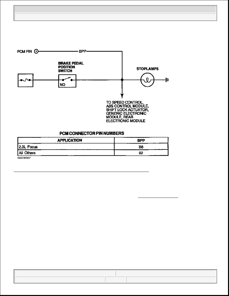
Fig. 227: Identifying Brake Pedal Position Switch Circuits (All Others) 
Courtesy of FORD MOTOR CO. 

Testing 

1) For KOER Only DTCs P0703 & P1703: Verify Brake Pedal Was Depressed 
These DTCs indicate that when brake pedal was applied during KOER on-demand self-test, BPP signal 
did not cycle high and low. Possible causes for this fault are: 

z

Open Or Short In BPP Circuit  

z

Open Or Short In Brakelight Circuit  

z

Faulty Powertrain Control Module (PCM)  

z

Faulty Rear Electronic Module (LS, Thunderbird & Windstar)  

z

Faulty Lighting Control Module (Town Car)  

z

Faulty BPP Switch  

z

Misadjusted Brake Switch  

z

Brake Pedal Not Applied During KOER On-Demand Self-Test 

NOTE:

For additional testing information, see DIAGNOSTIC AIDS.


2003 Ford Pickup F150 

2003 ENGINE PERFORMANCE Self-Diagnostics - CNG, Flex-Fuel & Gasoline


If brake pedal was not applied and released during KOER on-demand self-test, repeat KOER ON-
DEMAND SELF-TEST
. Depress and release brake pedal only once during test. If brake pedal was 
applied and released during KOER on-demand self-test, proceed as follows:  

z

On Town Car, diagnose Lighting Control Module (LCM) and/or related system. See SYSTEM 
TESTS in appropriate AUTOLAMP SYSTEMS article in ACCESSORIES & EQUIPMENT.  

z

On Windstar, diagnose Rear Electronic Module (REM) and/or related system. See SYSTEM 
TESTS in appropriate AUTOLAMP SYSTEMS article in ACCESSORIES & EQUIPMENT.  

z

On Expedition and Navigator, diagnose anti-lock brake system. See appropriate ANTI-LOCK 
article in BRAKES.  

z

On all others, go to step 3).  

2) For KOEO Only DTCs P0703 & P1703: Verify Brake Pedal Was Not Applied 
These DTCs indicate that BPP signal voltage was high during KOEO on-demand self-test. Possible 
causes for these faults are: 

z

Open Or Short In BPP Circuit  

z

Open Or Short In Brakelight Circuit  

z

Faulty Powertrain Control Module (PCM)  

z

Faulty Rear Electronic Module (LS & Windstar)  

z

Faulty Lighting Control Module (Town Car)  

z

Faulty BPP Switch  

z

Misadjusted Brake Switch  

z

Brake Pedal Applied During Entire KOEO On-Demand Self-Test  

If brake pedal was applied during KOEO on-demand self-test, repeat KOEO ON-DEMAND SELF-
TEST
. DO NOT apply brake pedal during KOEO on-demand self-test. If brake pedal was not applied 
during KOEO on-demand self-test, proceed as follows:  

z

On Town Car, diagnose Lighting Control Module (LCM) and/or related system. See SYSTEM 
TESTS in appropriate AUTOLAMP SYSTEMS article in ACCESSORIES & EQUIPMENT.  

z

On Windstar, diagnose Rear Electronic Module (REM) and/or related system. See SYSTEM 
TESTS in appropriate AUTOLAMP SYSTEMS article in ACCESSORIES & EQUIPMENT.  

z

On Expedition and Navigator, diagnose anti-lock brake system. See appropriate ANTI-LOCK 
article in BRAKES.  

z

On all others, turn ignition switch to ON position and go to next step.  

3) For Continuous Memory Only DTCs P0703, & For KOER & Continuous Memory Only DTC 
P1572: Check Operation Of Brakelights 
These DTCs indicate brake input rationality tests (one or both BPA or BPP switch inputs to PCM) failed 
to change when expected. Possible causes are: 

NOTE:

For additional testing information, see DIAGNOSTIC AIDS.

NOTE:

For additional testing information, see DIAGNOSTIC AIDS.


2003 Ford Pickup F150 

2003 ENGINE PERFORMANCE Self-Diagnostics - CNG, Flex-Fuel & Gasoline


z

Misadjusted Brake Switch  

z

Blown Fuse  

z

Faulty BPP Switch  

z

Faulty BPA Switch  

z

Open Or Short In BPP Circuit  

z

Open Or Short In BPA Circuit  

z

Faulty Powertrain Control Module (PCM)  

Check operation of brakelights. If brakelights operate normally, go to next step. If brakelights do not 
operate properly, on LS and Thunderbird, diagnose Rear Electronic Module (REM) and/or related system. 
See SYSTEM TESTS in appropriate AUTOLAMP SYSTEMS article in ACCESSORIES & 
EQUIPMENT. On all others, go to step 5) (brakelights inoperative), or step 7) (brakelights always on). 

4) Check For PCM BPP PID Cycling 
 
Turn ignition switch to OFF position. Connect scan tool to Data Link Connector (DLC). Turn ignition 
switch to ON position. Using scan tool, access BPP PID from PID/DATA MONITOR & RECORD 
menu. 

While observing BPP PID, apply and release brake pedal several times. If BPP PID does not cycle ON 
and OFF, go to step 10). If BPP PID cycles ON and OFF, go to step 14) (for DTC P1572), or go to TEST 
Z, step 1) (for all others). 

5) Check B+ Voltage To BPP Switch 
 
Ensure brakelight bulbs are okay. Disconnect BPP switch (located on brake pedal). Using a DVOM, 
measure voltage between B+ circuit at BPP switch harness connector and chassis ground. If voltage is 
more than 10 volts, go to next step. If voltage is 10 volts or less, check fuse for B+ circuit to BPP switch. 
If fuse is okay, repair open in B+ circuit to BPP switch. If fuse is blown, repair short to ground in B+ 
circuit, BPP or brakelight PWR circuit. See EXTERIOR LIGHTS in SYSTEM WIRING DIAGRAMS in 
ELECTRICAL. 

6) Verify Integrity Of BPP Switch 
 
Using a DVOM, measure resistance between appropriate BPP switch terminals. See Fig. 219-Fig. 227 . 
Observe resistance measurement while applying brake pedal. If resistance is 5 ohms or more with brake 
pedal applied, replace BPP switch. If resistance is less than 5 ohms with brake pedal applied, repair open 
circuit between BPP switch and brakelight ground. 

7) Verify BPP Switch Is Not Always Closed 
 
Disconnect BPP switch (located on brake pedal). Turn ignition switch to ON position. If brakelights are 
still illuminated, go to next step. If brakelights are now off, verify correct installation of BPP switch. If 

NOTE:

If BPP PID is not accessible, go to step 10).


2003 Ford Pickup F150 

2003 ENGINE PERFORMANCE Self-Diagnostics - CNG, Flex-Fuel & Gasoline


installation is okay, replace BPP switch. 

8) Check For Short To Power In PCM 
 
Turn ignition switch to OFF position. Disconnect PCM connector(s). Turn ignition switch to ON position. 
If brakelights are still illuminated, go to next step. If brakelights are now off, replace PCM. 

9) Check Brakelight Circuit For Short To Power In Harness 
 
Turn ignition switch to OFF position. Ensure PCM and BPP switch are disconnected. One at a time, 
disconnect modules associated with brakelight circuit. See WIRING DIAGRAMS. After disconnecting 
an associated module, turn ignition switch to ON position and check brakelights. Turn ignition switch to 
OFF position. Repeat until each associated module has been disconnected or brakelights turn off. If 
brakelights are still on after disconnecting all associated modules, repair short to power in brakelight 
circuit. See EXTERIOR LIGHTS article in ACCESSORIES & EQUIPMENT. If brakelights are off with 
associated module(s) disconnected, diagnose appropriate module and/or related system. Repair system or 
replace module as necessary. 

10) Check For BPP Circuit Cycling 
 
Turn ignition switch to OFF position. Disconnect PCM connector(s). Inspect connector for loose, 
damaged or corroded terminals. Repair as necessary. For Aviator, Explorer, LS, and Mountaineer (150-
pin PCM) with ABS-stability assist, measure DBA input at PCM harness connector and ground while 
applying and releasing the brake. For all others, using a DVOM, measure voltage between BPP circuit at 
PCM harness connector and chassis ground while applying and releasing brake pedal. If voltage does not 
cycle, repair open in BPP circuit to PCM. If voltage cycles, go to next step (Aviator, Explorer, LS, 
Mountaineer and Thunderbird), or replace PCM (all others). 

11) Check For BPA Circuit Cycling 
 
Ensure PCM connectors are disconnected. Using a DVOM, measure voltage between BPA circuit at PCM 
harness connector and chassis ground while applying and releasing brake pedal. If voltage does not cycle, 
go to next step. If voltage cycles, go to step 15). 

12) Check BPA Circuit For Open In Harness 
 
Disconnect BPA deactivator switch connector. Using a DVOM, measure resistance of BPA circuit 
between PCM harness connector and BPA deactivator switch harness connector. See Fig. 219-Fig. 227 . 
See WIRING DIAGRAMS. If resistance is less than 5 ohms, go to next step. If resistance is 5 ohms or 
more, repair open in BPA circuit between BPA switch and PCM. 

13) Check BPA Deactivator Switch 
 
Using a DVOM, measure resistance between BPA deactivator switch terminals while applying and 
releasing brake pedal. With brake pedal applied, resistance should be more than 10 k/ohms. With brake 
pedal released, resistance should be less than 5 ohms. If resistance is as specified, repair VPWR circuit to 
BPA deactivator switch. If resistance is not as specified, replace BPA deactivator switch. 


2003 Ford Pickup F150 

2003 ENGINE PERFORMANCE Self-Diagnostics - CNG, Flex-Fuel & Gasoline


Content   ..  1491  1492  1493  1494   ..