Ford F150 Pickup. Instruction - part 1491


  Index      Ford     Ford F150 Pickup - service and repair instruction 2003 year


Search            copyright infringement  


Content   ..  1489  1490  1491  1492   ..


Ford F150 Pickup. Instruction - part 1491


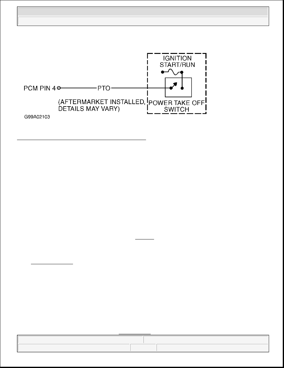
Fig. 218: Identifying PTO Circuit & Switch Schematic 
Courtesy of FORD MOTOR CO. 

Testing 

1) PTO PID Does Not Cycle: Check For Defective PTO Switch 
PTO signals PCM that additional load is being applied to engine. If PTO circuit failure occurs, a DTC 
may be set. Possible causes for this fault are: 

z

PTO Circuit Shorted To PWR In Aftermarket Switch Or VPWR  

z

Faulty Powertrain Control Module (PCM)  

Turn ignition switch to OFF position. Disconnect PTO switch connector. Using a DVOM, measure 
resistance between PTO switch terminals. See Fig. 218. With PTO switch in OFF position, resistance 
should be more than 10 k/ohms. With PTO switch in ON position, resistance should be less than 5 ohms. 
If resistance is as specified, go to next step. If resistance is not as specified, replace PTO switch. Refer to 
aftermarket component manufacturer for service information. Reconnect PTO switch connector. Perform 
DRIVE CYCLES. Ensure OBD-II DRIVE CYCLE is performed to verify repair. 

2) Check PTO Circuit For Short To VPWR 
 
Ensure ignition switch is in OFF position. Disconnect PCM connector. Inspect connector for loose, 
damaged or corroded terminals. Repair as necessary. Turn ignition switch to ON position. Using a 
DVOM, measure voltage between PTO circuit at PCM harness connector and negative battery terminal. If 
voltage is less than one volt, reconnect PCM and PTO switch connectors and go to step 4). If voltage is 
one volt or more, repair PTO circuit for short to VPWR. 

NOTE:

Diagnostic procedures beginning with step 1) are performed when 
directed here from TEST QA, step 20), or TEST QC, step 2).

NOTE:

Diagnostic procedures beginning with step 3) are performed when 
directed here from SYMPTOMS in TROUBLE SHOOTING - NO CODES - 


2003 Ford Pickup F150 

2003 ENGINE PERFORMANCE Self-Diagnostics - CNG, Flex-Fuel & Gasoline


3) MIL On: Check PTO PID 
Possible causes are: 

z

PTO Circuit Open  

z

PTO Circuit Shorted To Chassis Ground  

Turn ignition switch to OFF position. Connect scan tool to Data Link Connector (DLC). Turn ignition 
switch to ON position. Using scan tool, access PTO PID from PID/DATA MONITOR & RECORD. If 
PTO PID is available and displaying ON or OFF, go to step 1). If PTO PID is not available, go to step 9). 

4) Check PTO Circuit With Scan Tool 
Turn ignition switch to ON position. Engine may need to be started to engage PTO. Cycle PTO 
switch/handle while observing PTO PID. If PTO PID cycles ON, delays, then turns OFF, diagnose by 
symptom and repair as necessary. Go to SYMPTOMS in TROUBLE SHOOTING - NO CODES - CNG, 
FLEX-FUEL & GASOLINE article. If PTO PID value does not cycle as specified, go to next step. 

5) Check PTO Circuit For Short To Ground In Harness 
 
Turn ignition switch to OFF position. Disconnect PCM connector. Disconnect PTO switch connector. 
Disconnect scan tool from DLC. Using a DVOM, measure resistance of PTO circuit between PCM 
harness connector and negative battery terminal. If resistance is 10 k/ohms or less, repair short to ground 
in PTO circuit. If resistance is more than 10 k/ohms, go to step 7). 

7) Check PTO Circuit From PTO Switch Connector To PCM 
 
Reconnect PCM harness connector. Connect scan tool to DLC. Connect a jumper wire between positive 
battery terminal (B+) and PTO circuit at PTO switch harness connector. See Fig. 218. Turn ignition 
switch to ON position. Using scan tool, access PTO PID from PID/DATA MONITOR & RECORD. If 
PTO PID value is ON with jumper wire connected and OFF with jumper wire disconnected, PTO circuit 
is okay. Diagnose by symptom and repair as necessary. Go to SYMPTOMS in TROUBLE SHOOTING -
NO CODES - CNG, FLEX-FUEL & GASOLINE article. If PTO PID value is not as specified, go to next 
step. 

8) Check PTO Circuit Resistance 
 
Turn ignition switch to OFF position. Disconnect PCM connector. Using a DVOM, measure resistance of 
PTO circuit between PCM harness connector and PTO switch harness connector. See Fig. 218. If 
resistance is less than 5 ohms, replace PCM. If resistance is 5 ohms or more, repair open in PTO circuit. 

CNG, FLEX-FUEL & GASOLINE article.

NOTE:

This test step requires operating PTO. Refer to PTO manufacturer 
operating instruction for operating instructions and safety precautions.

NOTE:

A break in step numbering sequence occurs at this point. Procedure skips 
from step 5) to step 7). No test procedures have been omitted.


2003 Ford Pickup F150 

2003 ENGINE PERFORMANCE Self-Diagnostics - CNG, Flex-Fuel & Gasoline


9) Perform KOEO & KOER Self-Tests 
Perform KOEO ON-DEMAND SELF-TEST and KOER ON-DEMAND SELF-TEST . If any DTCs 
are present, service DTCs as necessary. See DIAGNOSTIC TROUBLE CODE DEFINITIONS. If no 
DTCs are present, go to next step. 

10) Perform OBD-II Drive Cycle With PTO Disengaged 
Ensure PTO is disengaged. Perform PCM RESET PROCEDURE under CLEARING CODES under 
SELF-DIAGNOSTIC SYSTEM. Perform DRIVE CYCLES. Ensure OBD-II DRIVE CYCLE is 
performed to verify repair. Retrieve Continuous Memory DTCs. If any DTCs are present, service DTCs 
as necessary. See 

DIAGNOSTIC TROUBLE CODE DEFINITIONS

. If no DTCs are present, fault 

cannot be duplicated at this time. MIL illumination may have been caused by engaging PTO (creating an 
engine load), while OBD-II monitors were running. If symptom is still present, go to TEST Z, step 1).  

TEST FD: BRAKE PEDAL POSITION SWITCH 

Diagnostic Aids 

Perform this test when directed by QUICK TEST. This test is intended to diagnose:  

z

Faulty BPP Switch  

z

Faulty Brake Pressure Applied (BPA) Deactivator Switch  

z

Wiring Harness Circuits (B(+), BPA, BPP, DBA, GND & Stoplamp PWR)  

z

Powertrain Control Module (PCM)  

Vehicles equip with stability assist will typically have the BPP switch input connected to the Anti-Lock Brake 
(ABS)-traction control\stability assist module. The stability assist portion of the ABS module will interpret the 
BPP switch input along with other ABS inputs and generate a output called the Driver Brake Application 
(DBA) signal. The DBA signal is typically sent to the PCM and to other BPP signal users. Correct stop lamp 
operation on stability assist equip vehicles are control by the ABS-traction control\stability assist module and\or 
stop lamp relay circuitry. When diagnosing these types of system always refer to the appropriate ANTI-LOCK 
article in BRAKES for ABS description and operation information and to the vehicle wiring schematic for BPP, 
DBA and stop lamp circuit information. 

NOTE:

This test step is for diagnosing PTO when vehicle does not support PTO 
circuit or PTO PID.

NOTE:

This test step will determine if applying an extra load on engine, such as 
operating PTO, caused a Continuous Memory DTC to be stored.

NOTE:

After each service or repair procedure has been completed, reconnect all 
components. Clear DTCs and repeat QUICK TEST procedures to ensure all EEC-
V systems are working properly and DTCs are no longer present.

NOTE:

On Town Car and Windstar, PCM receives BPP switch information through the 
Standard Corporate Protocol (SCP) link. This system test will only verify that 


2003 Ford Pickup F150 

2003 ENGINE PERFORMANCE Self-Diagnostics - CNG, Flex-Fuel & Gasoline


Fig. 219: Identifying Brake Pedal Position Switch Circuits (Aviator, Explorer & Mountaineer - Without 
Stability Assist)
 
Courtesy of FORD MOTOR CO. 

self-test was performed correctly. For circuit wire color identification, see 
WIRING DIAGRAMS.


2003 Ford Pickup F150 

2003 ENGINE PERFORMANCE Self-Diagnostics - CNG, Flex-Fuel & Gasoline


Content   ..  1489  1490  1491  1492   ..