Ford F150 Pickup. Instruction - part 1470


  Index      Ford     Ford F150 Pickup - service and repair instruction 2003 year


Search            copyright infringement  


Content   ..  1468  1469  1470  1471   ..


Ford F150 Pickup. Instruction - part 1470


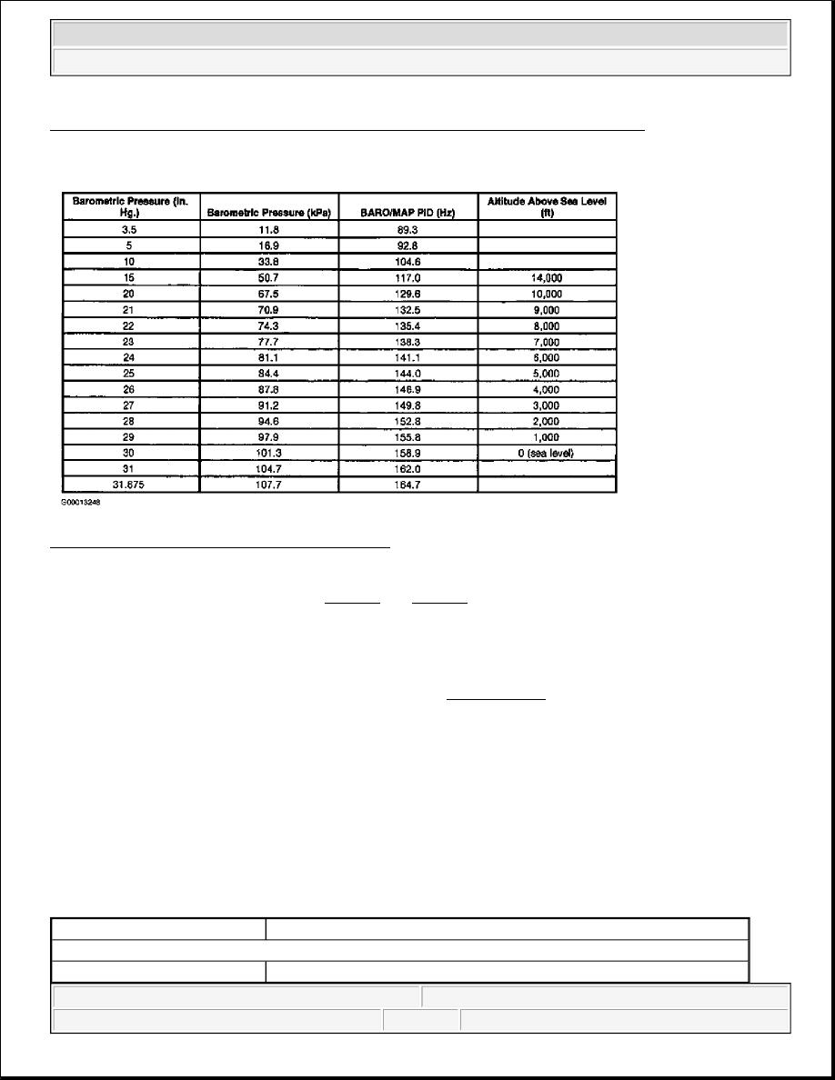
Fig. 184: Identifying MAF Sensor Wiring Harness Connector & Circuits (All Others) 
Courtesy of FORD MOTOR CO. 

Fig. 185: Barometric Pressure Conversion Chart 
Courtesy of FORD MOTOR CO. 

For Focus 2.3L, LS and Thunderbird, see Fig. 173 and Fig. 174 . 

TEST DD: FUEL RAIL PRESSURE SENSOR 

Diagnostic Aids 

Perform this test when directed by QUICK TEST. This test is intended to diagnose the following:  

z

FRP Sensor  

z

Wiring Harness Circuits (FRP & SIG RTN)  

z

Powertrain Control Module (PCM)  

FRP SENSOR VOLTAGE-TO-FUEL PRESSURE CONVERSION 

NOTE:

After each service or repair procedure has been completed, reconnect all 
components. Clear DTCs and repeat QUICK TEST procedures to ensure all EEC-
V systems are working properly and DTCs are no longer present.

Volts

psi (kPa)

Natural Gas Vehicles

4.5

150 (1034)


2003 Ford Pickup F150 

2003 ENGINE PERFORMANCE Self-Diagnostics - CNG, Flex-Fuel & Gasoline


Testing 

1) For KOEO & KOER Only DTC P0192: Verify DTC With FRP PID 
This DTC indicates FRP voltage fell below a minimum calibrated limit and a calibrated minimum amount 
of time during Comprehensive Component Monitor (CCM). Possible causes for this fault are: 

z

FRP Signal Shorted To SIG RTN Or PWR GND  

z

FRP Signal Circuit Open (NGV Only)  

z

Low Fuel Pressure (NGV Only)  

z

Faulty FRP Sensor  

z

Faulty PCM  

Ensure vehicle has fuel (natural gas vehicles). Turn ignition switch to ON position. Using scan tool, 
access FRP PID from PID/DATA MONITOR & RECORD menu. If FRP PID voltage is less than .2 volt, 
go to next step (natural gas vehicles), or step 3) (all others). If FRP PID voltage is .2 volt or more, 
concern is intermittent. Go to step 13). 

2) Check Fuel Pressure (Natural Gas Vehicles) 
 

4.1

140 (965)

3.7

130 (896)

3.3

120 (827)

2.9

110 (758)

2.5

100 (689)

2.1

90 (620)

1.7

80 (551)

1.3

70 (482)

0.9

60 (413)

0.5

50 (344)

0.1

40 (275)

0.0

37.6 (259)

Gasoline Vehicles

4.5

70 (482)

3.9

60 (413)

3.4

50 (344)

2.8

40 (275)

2.2

30 (207)

1.6

20 (138)

1.1

10 (69)

0.5

0.0 (0.0)

NOTE:

For additional testing information, see DIAGNOSTIC AIDS.


2003 Ford Pickup F150 

2003 ENGINE PERFORMANCE Self-Diagnostics - CNG, Flex-Fuel & Gasoline


Start engine. Access FRP PID and monitor fuel pressure. If fuel pressure reading is 80-120 psi (552-827 
kPa), go to next step. If fuel pressure reading is not 80-120 psi (552-827 kPa), go to TEST HB, step 1). 

3) Generate Opposite Signal 
 
Turn ignition switch to OFF position. Disconnect FRP sensor connector. Connect a jumper wire between 
FRP SIGNAL and VREF circuits at FRP sensor harness connector. See Fig. 186

Turn ignition switch to ON position. Using scan tool, access FRP V PID from PID/DATA MONITOR & 
RECORD menu. If FRP V PID voltage is more than 4.6 volts and vehicle is a no start, go to step 5). All 
others, replace FRP sensor. If FRP V PID voltage is 4.6 volts or less, disconnect jumper wire and go to 
next step. 

4) Check VREF Voltage To FRP Sensor 
 
Ensure FRP sensor is disconnected and ignition switch is turned to ON position. Using a DVOM, 
measure voltage between VREF and SIG RTN circuits at FRP sensor harness connector. See Fig. 186 or 
Fig. 187 . If voltage is 4-6 volts, go to next step. If voltage is not 4-6 volts, reconnect sensor and go to 
TEST C, step 1). 

5) Check FRP Circuit For Open In Harness 
 
Turn ignition switch to OFF position. Leave FRP sensor disconnected. Disconnect PCM connector(s). 
Inspect connector for loose, damaged or corroded terminals. Repair as necessary. Using a DVOM, 
measure resistance of FRP circuit between FRP sensor harness connector and PCM harness connector. 
See PCM CONNECTOR IDENTIFICATION and Fig. 186 or Fig. 187 . If resistance is less than 5 
ohms, go to next step. If resistance is 5 ohms or more, repair open in FRP circuit. 

6) Check FRP Circuit For Short To PWR GND Or SIG RTN 
 
Using a DVOM, measure resistance between FRP and SIG RTN terminals at PCM harness connector. 
Also, measure resistance of FRP circuit between negative battery terminal and PCM harness connector 
terminal. See PCM CONNECTOR IDENTIFICATION and Fig. 186 or Fig. 187 . If both resistance 
measurements are more than 10 k/ohms on no starts, go to TEST HB step 19). All others, replace PCM. If 
either resistance measurement is 10 k/ohms or less, repair short in affected circuit. 

7) For KOEO & KOER Only DTC P0193: Check FRP V PID Value 
This DTC indicates FRP voltage fell below a minimum calibrated limit and a calibrated minimum amount 

NOTE:

Fuel Rail Pressure (FRP) sensor may also be known as Injection Pressure 
(IP) sensor.

NOTE:

If a scan tool communication concern exists, remove jumper wire and go 
to step 24).

NOTE:

For additional testing information, see DIAGNOSTIC AIDS.


2003 Ford Pickup F150 

2003 ENGINE PERFORMANCE Self-Diagnostics - CNG, Flex-Fuel & Gasoline


of time during Comprehensive Component Monitor (CCM). Possible causes for this fault are: 

z

FRP Signal Shorted To VREF Or VPWR  

z

FRP Signal Open (Gasoline Only)  

z

Low Fuel Pressure (NGV Only)  

z

Faulty FRP Sensor  

z

Faulty PCM  

z

High Fuel Pressure (Possible Faulty Fuel Pressure Regulator - NGV Only)  

Turn ignition switch to ON position. Using scan tool, access FRP V PID from PID/DATA MONITOR & 
RECORD menu. FRP V PID voltage should be more than 4.5 volts on natural gas vehicles, and more 
than 4.8 volts on gasoline vehicles. If FRP V PID voltage is as specified, go to next step (gasoline 
vehicles), and step 9) (natural gas vehicles). If FRP V PID voltage is not as specified, fault may be 
intermittent. Go to step 14). 

8) Check FRP Sensor For Fuel Leaks 
 
Turn ignition switch to OFF position. Remove vacuum hose from FRP sensor. Inspect sensor and vacuum 
hose for fuel. If any fuel is present, replace FRP sensor. If no fuel is present, go to step 10). 

9) Check Fuel Pressure (Natural Gas Vehicles) 
Start engine. Using scan tool, access FRP V PID from PID/DATA MONITOR & RECORD menu and 
monitor pressure. If fuel pressure is more than 150 psi (1034 kPa), go to TEST HB, step 1). If fuel 
pressure is 150 psi (1034 kPa) or less, go to next step. 

10) Simulate Opposite FRP Signal To PCM 
 
Turn ignition switch to OFF position. Disconnect FRP sensor connector. Connect jumper wire between 
FRP and SIG RTN terminals at FRP sensor harness connector. See Fig. 186 or Fig. 187 . Turn ignition 
switch to ON position. Using scan tool, access FRP V PID from PID/DATA MONITOR & RECORD 
menu. 

If FRP V PID voltage is less than .2 volt, replace FRP sensor. If FRP V PID voltage is .2 volt or more, go 
to step 12). 

NOTE:

In the following test, if natural gas vehicle is not equipped with Schrader 
valve for fuel pressure gauge installation, use scan tool and access FRP 
PID from PID/DATA MONITOR & RECORD menu to monitor fuel pressure.

NOTE:

If a scan tool communication concern exists, remove jumper wire and go 
to step 24).

NOTE:

For additional testing information, see DIAGNOSTIC AIDS.

NOTE:

Before performing this step, check fuel system and repair any external 


2003 Ford Pickup F150 

2003 ENGINE PERFORMANCE Self-Diagnostics - CNG, Flex-Fuel & Gasoline


Content   ..  1468  1469  1470  1471   ..