Ford F150 Pickup. Instruction - part 1345


  Index      Ford     Ford F150 Pickup - service and repair instruction 2003 year


Search            copyright infringement  


Content   ..  1343  1344  1345  1346   ..


Ford F150 Pickup. Instruction - part 1345


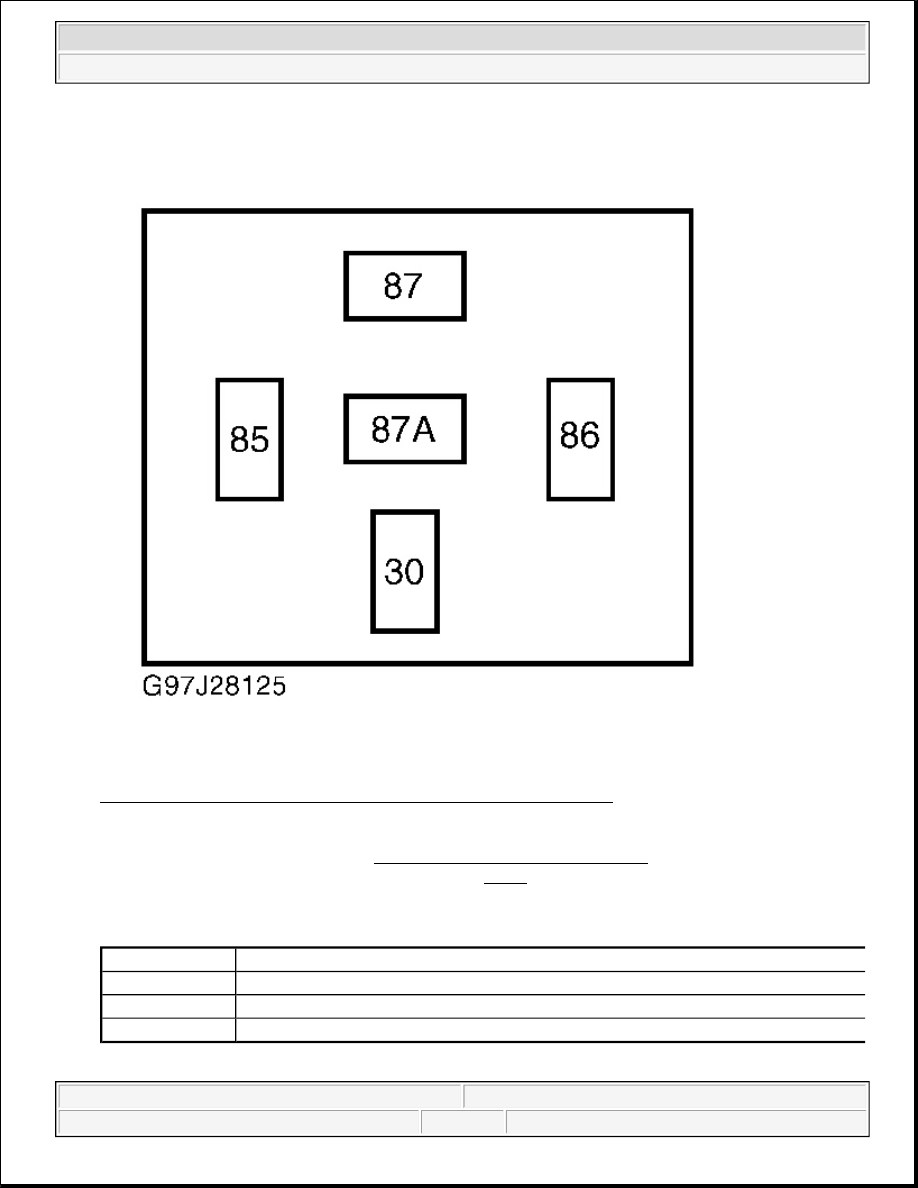
Fig. 7: Identifying Fuel Pump Relay Harness Connector Terminals 
Courtesy of FORD MOTOR CO. 

1. Remove fuel pump (valve) relay. See FUEL PUMP RELAY LOCATION table. Connect a jumper wire 

between fuel pump relay cavities No. 30 and 87. See Fig. 7. This will cause tank valves to open and 
pressurize fuel system. Remove jumper wire and go to next step. 

FUEL PUMP RELAY LOCATION 

2. Reinstall fuel pump relay. Using Combustible Gas Detector (134-00049), check spring lock coupling and 

Application

Location

Crown Victoria

In Relay Center Box No. 1, On Left Side Wheelwell In Engine Compartment

Econoline

In Battery Junction Box, On Left Side Of Engine Compartment

F150

In Battery Junction Box, On Rear Left Side Of Engine Compartment


2003 Ford Pickup F150 

2003 ENGINE PERFORMANCE System & Component Testing - CNG


fuel injection supply manifold to fuel injector connections for leaks. If a leak is detected, verify 
connection is engaged properly, then retest. If leak remains, repair as necessary and retest.  

Fuel Tanks, Filter & Lines 

Using combustible gas detector, check fuel tank(s), coalescent filter and fuel line connections for leaks. If a leak 
is detected, verify that fittings are tightened properly, then retest. If leak is still present, inspect "O" ring, "O" 
ring seat and sealing surfaces for any damage, distortion or contamination. Repair as necessary and retest. 

Rear/Upper Fuel Tank Rack Vapor Vent Box (Crown Victoria) 

1. Install the Rotunda Pressure Test Adaptor (134-00122 - part of NGV Pressure and Venting Kit) to the 

upper tank rack flexible vent tube. Install the Rotunda Evaporative Emission Tester (134-00056) to the 
pressure test adaptor.  

2. Pressurize the vapor vent box to 17 in. H2O (5 kPa).  

3. Monitor the pressure for two minutes. The pressure should not drop more than 6 in. H2O (1.5 kPa).  

4. If the pressure drops in excess of 6 in. H2O (1.5 kPa), apply a soapy water solution around the vapor vent 

box gasket and seals to pinpoint the leak. Install a new gasket or seals as applicable.  

FUEL TANK INSPECTION (IN-VEHICLE) 

1. Raise and support vehicle. Examine vehicle underbody and chassis in general area near fuel tank(s) for 

any indication of collision damage, malfunction, fire or excessive mud/dirt accumulation. Examine fuel 
tank stone/heat shield for any indication of collision damage, malfunction, fire or excessive mud/dirt 
accumulation. Remove fuel tank stone/heat shield. Examine fuel tank(s) and stone/heat shield interior for 
any foreign objects (such as stones or gravel) or foreign materials (such as mud, salt, liquids or chemical 
residue).  

2. Remove any foreign material, using only a clean, dry cloth. Remove all foreign objects. DO NOT use 

water or any cleaners. Examine fuel tank labels for tank expiration date. Use a light and mirror to access 
labels hidden from normal view. If expiration date has been exceeded, condemn tank, using procedures in 
step 8. 

3. Inspect tank sidewall and dome ends, following general guidelines set forth in Compressed Gas 

Association Pamphlet C6.2. Inspect tank(s) for abrasions, dents, cracking, blistering or peeling of clear 

NOTE:

Verify system pressure is no less than 1500 psi (105.5 kg/cm

2

 ). If system 

pressure is less than 1500 psi (105.5 kg/cm

2

 ), refuel vehicle.

NOTE:

The following procedure is an in-vehicle visual inspection for natural gas fuel 
cylinders. A 3 year, 36,000-mile (whichever occurs first) inspection interval is 
assumed.

NOTE:

Compressed Natural Gas Pamphlet C6.2 can be obtained from 
Compressed Gas Association, Inc., 1725 Jefferson Davis Highway, 
Arlington, VA 22202-4102.


2003 Ford Pickup F150 

2003 ENGINE PERFORMANCE System & Component Testing - CNG


coating, corrosion, cracks or gouges in metal dome, cracks in fiberglass overwrap, impact damage 
(cracking) in fiberglass overwrap, cuts or gouges in fiberglass overwrap, exposed fibers, delamination 
(separating) of fiberglass overwrap, discoloration of fiberglass overwrap, and/or fire or heat damage, such 
as charring or discoloration.  

4. If any flaws are detected, measure depth and length of flaw in accordance with Compressed Gas 

Association Pamphlet C6.2 guidelines. If any of the flaws cannot be completely measured in vehicle, tank 
must be removed from vehicle for further inspection. If tanks have been or are suspected of having been 
exposed to a corrosive chemical spill, tank must be removed from vehicle for further inspection of 
complete composite surface, including area under tank straps. If there is any indication of chemical 
attack, such as blistering, cracking or delamination, tanks must be condemned and replaced with new 
tanks.  

5. The acceptance criteria for cuts and abrasions are different from those listed in Section 6.5.1 of 

Compressed Gas Association Pamphlet C6.2. These tanks have extra epoxy resin and a clear coat to 
reduce sensitivity to surface damage. The following are composite wrap inspection criteria: 

z

Level 1 Abrasions 
 
These are defined as minor abrasions, such as scuffs less than .010" (0.254 mm) deep, and are 
acceptable without repair. 

z

Level 2 Abrasions 
 
These are defined as abrasions having some exposed fibers or flat spots with a depth between .010-
.030" (.254-.762 mm). Level 2 abrasions must be repaired before tank is returned to service. 

z

Level 1 Cuts 
 
These are defined as cuts or scratches less than .010" (.254 mm) deep and are acceptable without 
repair regardless of length, number or direction. 

z

Level 2 Cuts 
 
These cuts have a maximum depth of .030" (.762 mm) and a maximum length of 8" (203 mm). 
Level 2 cuts must be repaired before tank is returned to service.  

6. Repair damage to composite wrap as follows: 

z

Level 2 cuts and abrasions are to be coated with epoxy resin. Mix and apply commercial room 
temperature cure, 2-component epoxy resin according to manufacturer's instructions. Frayed fibers 
must be cut away before application of epoxy resin.  

z

Tanks with damage exceeding Level 2 must be condemned using procedures in step 8.  

z

The criteria for other damage to composite wrap are defined in Compressed Gas Association 
Pamphlet C6.2.  

7. The metal tank ends are protected with a multi-coat system using epoxy and polyurethane coatings. Chips 

in coating must be evaluated and repaired. Metal tank end external inspection criteria are as follows: 

z

Level 1 Chips 


2003 Ford Pickup F150 

2003 ENGINE PERFORMANCE System & Component Testing - CNG


These are chips or abrasions which do not penetrate Black epoxy coating. The steel or Gray primer 
has not been exposed. Level 1 chips require no repair. 

z

Level 2 Chips 
 
These are chips or abrasions which penetrate Black epoxy coating and must be repaired as follows 
to prevent corrosion: 

a. Sand damaged area to remove rust and rough up surrounding coating.  

b. Clean damaged area with a commercial pre-paint cleaning solvent.  

c. Apply a zinc-rich, cold galvanizing compound (Rust-Oleum(tm) Zinc-Rich or equivalent 

commercial product).  

z

Dents 
 
Tanks with dents to metal ends which are more than .060" (1.524 mm) in depth must be removed 
from service and condemned using procedures in step 8. 

z

Gouges 
 
Tanks with sharp gouges penetrating coating and into metal liner must be removed from service 
and condemned using procedures in step 8.  

8. Condemned tanks, whether due to damage or expiration, shall be removed from vehicle and destroyed as 

follows: 

a. Vent and remove fuel tanks. See appropriate REMOVAL & INSTALLATION article.  

b. Remove fuel tank solenoid valve. See appropriate REMOVAL & INSTALLATION article.  

c. Purge fuel tank with compressed air for 30 seconds.  

d. Destroy fuel tank by drilling a .50" (12.7 mm) diameter hole in fuel tank sidewall.  

9. Examine fuel tank straps for correct positioning of rubber isolators. Replace rubber isolators as necessary. 

When completed, record date, vehicle mileage and results of fuel tank inspection.  

UNABLE TO VENT FUEL TANKS OR FUEL LINES 

Pre-Inspection 

WARNING:

When venting Compressed Natural Gas (CNG) from system, fuel filler 
neck venting kit must be connected to a vent stack that allows CNG to be 
vented outside of repair shop. Vent stack installation must be approved 
by local authorities.

NOTE:

A DVOM, New Generation Star (NGS) tester and NGV Pressure and Venting Kit 
(134-00114) are necessary to perform the following test procedures. NGV 
pressure and venting kit includes Rotunda Fuel Filler Neck Venting Kit (134-
00117), Grounding Cable (134-00121), Electrical Harness for Venting Tanks (134-


2003 Ford Pickup F150 

2003 ENGINE PERFORMANCE System & Component Testing - CNG


Content   ..  1343  1344  1345  1346   ..