Ford F150 Pickup. Instruction - part 1279


  Index      Ford     Ford F150 Pickup - service and repair instruction 2003 year


Search            copyright infringement  


Content   ..  1277  1278  1279  1280   ..


Ford F150 Pickup. Instruction - part 1279


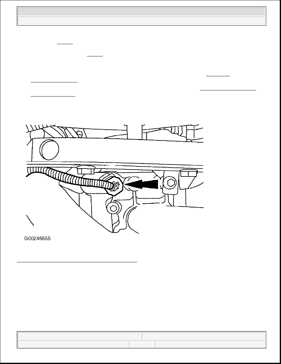
sensor. See Fig. 11 . Disconnect generator wiring. Disconnect Throttle Position (TP) sensor. Remove 
bolts retaining ignition coils and remove ignition coils. Remove LPG fuel injection supply manifold and 
fuel injector sleeves. See Fig. 12 .  

4. Install NEW "O" rings onto fuel injectors. Lightly lubricate "O" rings with clean engine oil. DO NOT use 

silicone-based lubricant. To complete installation, reverse removal procedure. Ensure injectors and/or 
injector sleeves are properly seated. Tighten fuel rail bolts to specification. See TORQUE 
SPECIFICATIONS
 .  

5. After installation is complete, fuel lines and fittings must be leak tested. See LEAK TEST - ALL BI-

FUEL VEHICLES under FUEL SYSTEMS in SYSTEM & COMPONENT TESTING - BI-FUEL - 
GASOLINE/CNG article.  

Fig. 11: Locating ECT Sensor Electrical Connector 
Courtesy of FORD MOTOR CO. 


2003 Ford Pickup F150 

2003 ENGINE PERFORMANCE Removal & Installation - F150 Pickup - Bi-Fuel - Gasoline/LPG


Fig. 12: Locating LPG Fuel Injection Supply Manifold 
Courtesy of FORD MOTOR CO. 

FUEL TANK 

Removal & Installation 

1. Release fuel pressure. See FUEL SYSTEM PRESSURE RELEASE . Disconnect negative battery 

cable. Remove in-bed tank assembly cover. Disconnect fuel lines. See Fig. 13 . Disconnect fuel level 
sender connector. See Fig. 14 . Place matching marks on upper bed mounted tank straps and tank(s). 
Remove upper in-bed fuel tank straps. See Fig. 15 . Position Floor Crane (014-00072), Separator Lift Bar 
(303-F054), and Lifting Sling (100-D008) over fuel tank. Carefully raise fuel tank assembly from vehicle. 

2. To install, reverse removal procedure. After installation is complete, fuel lines and fittings must be leak 

tested. See LEAK TEST - ALL BI-FUEL VEHICLES under FUEL SYSTEMS in SYSTEM & 
COMPONENT TESTING - BI-FUEL - GASOLINE/CNG article. 

NOTE:

On single tank systems, fuel tank must remain level or the fuel float will 
not read accurately.


2003 Ford Pickup F150 

2003 ENGINE PERFORMANCE Removal & Installation - F150 Pickup - Bi-Fuel - Gasoline/LPG


Fig. 13: Locating Fuel Lines 
Courtesy of FORD MOTOR CO. 

Fig. 14: Locating Fuel Level Sender Connector 
Courtesy of FORD MOTOR CO. 


2003 Ford Pickup F150 

2003 ENGINE PERFORMANCE Removal & Installation - F150 Pickup - Bi-Fuel - Gasoline/LPG


Fig. 15: Locating Fuel Tank Strap Bolts (Dual Tank Shown; Single Tank Is Similar) 
Courtesy of FORD MOTOR CO. 

LOCKOFF SOLENOID 

VAPORIZER (LPG FUEL HEATER) 

Removal & Installation 

1. Release fuel pressure. See LIQUEFIED PETROLEUM GAS FUEL LINE VENTING under FUEL 

SYSTEM PRESSURE RELEASE. Disconnect negative battery cable. Drain cooling system.  

2. Disconnect the vaporizer vent line. See Fig. 16 . Disconnect the vaporizer coolant hoses. See Fig. 17 . 

Disconnect the fuel lines from the vaporizer. See Fig. 18 . Disconnect electrical connector to cold start 
heater. See Fig. 19 . Remove 2 bolts retaining vaporizer and remove vaporizer assembly. See Fig. 20 .  

3. Install vaporizer and 2 bolts. Connect electrical connector to cold start heater. Connect fuel lines and 

coolant hoses to vaporizer. Connect vaporizer vent line. 

NOTE:

Removal and installation information is not available from manufacturer.

WARNING:

Always use NEW copper washers when installing vaporizer assembly. 
Reusing copper washers may cause sealing issues and LPG leaks in 
engine compartment.


2003 Ford Pickup F150 

2003 ENGINE PERFORMANCE Removal & Installation - F150 Pickup - Bi-Fuel - Gasoline/LPG


Content   ..  1277  1278  1279  1280   ..