Dodge Sprinter. Manual - part 88


  Index      Dodge     Dodge Sprinter / Mercedes-Benz - service repair manual 2006 year


Search            


Content   ..  86  87  88  89   ..


Dodge Sprinter. Manual - part 88


(5) Remove the washer supply hose from the

barbed outlet nipple of the washer pump/motor and
allow the washer fluid to drain into a clean container
for reuse.

(6) Disengage the washer supply hose from the

routing trough integral to the top of the washer res-
ervoir.

(7) Remove the nut and washer that secures the

top of the washer reservoir to the stud nut on the
right inner fender.

(8) Pull the washer reservoir inboard far enough to

disengage the reservoir from the stud nut.

(9) Tilt the washer reservoir forward far enough to

disengage the rear mounting post from the grommet
in the dash panel.

(10) Lift the washer reservoir upward far enough

to disengage the lower mounting post from the grom-
met in the top of the right front wheel house.

(11) Remove the washer reservoir from the engine

compartment.

INSTALLATION

(1) Position the washer reservoir into the engine

compartment.

(2) Engage the lower mounting post of the washer

reservoir into the grommet in the top of the right
front wheel house (Fig. 22).

(3) Engage the rear mounting post of the washer

reservoir into the grommet in the dash panel.

(4) Position the washer reservoir mounting hole

over the stud nut on the right inner fender (Fig. 21).

(5) Install and tighten the nut and washer that

secures the top of the washer reservoir to the stud
nut on the right inner fender. Tighten the nut to 6
N·m (50 in. lbs.).

(6) Reconnect the washer supply hose to the

barbed outlet nipple of the washer pump/motor.

(7) Engage the washer supply hose into the rout-

ing trough integral to the top of the washer reservoir.

(8) Reconnect the vehicle wire harness connector

for the washer pump/motor unit to the motor connec-
tor receptacle.

(9) Engage the vehicle wire harness into the rout-

ing clip integral to the front of the washer reservoir.

(10) Reinstall the upper turbocharger heat shield

and the upper air cleaner housing into the engine
compartment (Fig. 20).

(11) Refill the washer reservoir with the washer

fluid drained from the reservoir during the removal
procedure.

(12) Reconnect the battery negative cable.

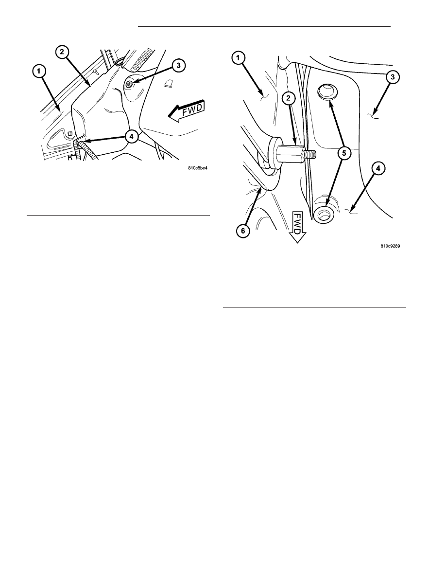
Fig. 21 Washer Reservoir Remove/Install

1 - RIGHT INNER FENDER
2 - WASHER RESERVOIR
3 - NUT & WASHER
4 - ROUTING CLIP

Fig. 22 Washer Reservoir Mounting

1 - RIGHT INNER FENDER
2 - STUD NUT
3 - DASH PANEL
4 - RIGHT FRONT WHEEL HOUSE
5 - GROMMET (2)
6 - HOOD PROP

8R - 22

WIPERS/WASHERS

VA

WIPER ARM

DESCRIPTION

The wiper arms are the rigid members located

between the wiper pivots that protrude from the cowl
top panel near the base of the windshield and the
wiper blades on the windshield glass (Fig. 23). These
wiper arms feature an over-center hinge that allows
easy access to the windshield glass for cleaning. The
wiper arm has a die cast metal pivot end with a
large tapered mounting hole at one end. A removable
molded black plastic pivot cover fits loosely over and
pivots on the wiper arm hinge pin, then snaps over
the pivot end to conceal the wiper arm retaining nut.

The wide end of a tapered, stamped steel channel

hinges on and is secured with a hinge pin to the
pivot end of the wiper arm. One end of a long, rigid,
stamped steel strap, with a small hole near its pivot
end, is riveted and crimped within the narrow end of
the stamped steel channel. The tip of the wiper blade
end of this strap is bent back under itself to form a
small hook. Concealed within the stamped steel
channel, one end of a long spring is engaged with a

wire hook on the underside of the die cast pivot end,
while the other end of the spring is hooked through
the small hole in the steel strap. The entire wiper
arm has a satin black finish applied to all of its vis-
ible surfaces.

Near the hook of the wiper arm steel strap is a

locating hole for the washer nozzle that is mounted
on the wiper arm. A U-shaped molded plastic guard
snaps onto the underside of the strap to conceal and
protect the washer nozzle hose. There are also two
small molded plastic washer nozzle hose routing
brackets clipped onto the underside of the wiper arm
pivot end.

The wiper arms for this model are unequal in

length, with the longer arm being installed on the
left (driver) side of the windshield. A wiper arm can-
not be adjusted or repaired. If damaged or faulty, the
entire wiper arm unit must be replaced. The washer
nozzle, nozzle hose, routing brackets, and pivot end

Fig. 23 Wiper Arm

1 - HOOK

7 - CHANNEL

2 - STRAP

8 - COVER

3 - WASHER HOSE

9 - PIVOT END

4 - BRACKET (2)

10 - GUARD

5 - HINGE PIN

11 - WASHER NOZZLE

6 - TENSION SPRING

VA

WIPERS/WASHERS

8R - 23

cover are available for individual service replace-
ment.

OPERATION

The wiper arms are designed to mechanically

transmit the motion from the wiper pivots to the
wiper blades. The wiper arm must be properly
indexed to the wiper pivot in order to maintain the
proper wiper blade travel on the glass. The tapered
mounting hole in the wiper arm pivot end interlocks
with the serrations on the outer circumference of the
wiper pivot shaft, allowing positive engagement and
finite adjustment of this connection. The mounting
nut locks the wiper arm to the threaded end of the
wiper pivot shaft. The spring-loaded wiper arm hinge
controls the down-force applied through the tip of the
wiper arm to the wiper blade on the glass. The hook
formation on the tip of the wiper arm provides a cra-
dle for securing and latching the wiper blade pivot
block to the wiper arm.

REMOVAL

(1) Disconnect the washer nozzle hose from the

elbow fitting on the cowl top panel near the pivot end
of the wiper arm (Fig. 24).

CAUTION: The use of a screwdriver or other prying
tool to remove a wiper arm may distort it. This dis-
tortion could allow the arm to come off of the wiper
pivot during wiper operation, regardless of how
carefully it is reinstalled.

(2) Unsnap the end of the pivot cover from the

wiper blade pivot end, then pull the cover away from
the wiper arm hinge pin to remove the cover from
the wiper blade.

(3) Remove the nut that secures the wiper arm to

the wiper pivot shaft.

(4) If necessary, use a suitable battery terminal

puller to disengage the wiper arm from the wiper
pivot shaft (Fig. 25).

(5) Remove the wiper arm pivot end from the

wiper pivot shaft.

INSTALLATION

NOTE: Be certain that the wiper motor is in the park
position before attempting to install the wiper arms.
Turn the ignition switch to the On position and
move the right (wiper) control stalk of the multi-
function switch to its Off position. If the wiper piv-
ots move, wait until they stop moving, then turn the
ignition switch back to the Off position. The wiper
motor is now in its park position.

NOTE: The wiper arms and wiper blades for this
model are both unequal in length, with the longer
arm and blade being installed on the left (driver)
side of the windshield.

(1) The wiper arms must be indexed to the wiper

pivot shafts with the wiper motor in the park posi-
tion to be properly installed. Position the wiper arm
pivot ends onto the wiper pivots so that the lower
edge of the wiper arm tip is aligned with the black
wiper alignment line located near the lower edge of
the windshield glass (Fig. 24).

(2) Once the wiper blade is aligned, lift the wiper

arm away from the windshield slightly to relieve the
spring tension on the pivot end and push the pivot
hole in the pivot end of the arm down firmly and
evenly over the wiper pivot shaft. Gently lower the
wiper arm until the wiper blade rests on the glass.

Fig. 24 Wiper Arm Remove/Install

1 - PIVOT COVER
2 - NUT
3 - PIVOT SHAFT
4 - WASHER NOZZLE HOSE
5 - ELBOW FITTING
6 - WIPER ARM

Fig. 25 Wiper Arm Puller - Typical

1 - WIPER ARM
2 - WIPER PIVOT SHAFT
3 - BATTERY TERMINAL PULLER

8R - 24

WIPERS/WASHERS

VA

(3) Install and tighten the nut that secures the

wiper arm to the wiper pivot shaft. Tighten the nut
to 24 N·m (18 ft. lbs.).

(4) Wet the windshield glass, then operate the wip-

ers. Move the right (wiper) control stalk of the multi-
function switch to the Off position, then check for the
correct wiper arm position and readjust as required.

(5) Engage the pivot cover with the wiper arm

hinge pin, then push the pivot end of the cover down
firmly and evenly until it snaps over the wiper blade
pivot end.

(6) Reconnect the washer nozzle hose to the elbow

fitting on the cowl top panel near the pivot end of the
wiper arm.

VA

WIPERS/WASHERS

8R - 25


Content   ..  86  87  88  89   ..