Dodge Sprinter. Manual - part 24


  Index      Dodge     Dodge Sprinter / Mercedes-Benz - service repair manual 2006 year


Search            


Content   ..  22  23  24  25   ..


Dodge Sprinter. Manual - part 24


edge of the diaphragm is secured to the housing. The
booster push rod, which connects the booster to the
brake pedal and master cylinder, is attached to the
center of the diaphragm. A check valve is used in the
booster outlet connected to the engine intake mani-
fold. Power assist is generated by utilizing a combi-
nation of vacuum and atmospheric pressure to boost
brake assist.

REMOVAL

(1) Using a suction gun remove as much brake

fluid from the reservoir as possible.

(2) Disconnect the brake level switch electrical

connector.

(3) Remove the brake lines from the master cylin-

der Seal off the ends and bore holes with plugs.

(4) Remove the master cylinder from the booster.
(5) Remove the booster vacuum hose and check

valve (Fig. 23).

(6) Remove the pedal push rod clip (Fig. 23).
(7) Remove the booster mounting nuts (Fig. 23).
(8) Remove the booster from the vehicle.

INSTALLATION

(1) Install the brake booster to the vehicle.
(2) Install the booster mounting nuts (Fig. 23).

Tighten to 25 N·m (221 in.lbs.).

(3) Install the push rod pin & clip (Fig. 23).
(4) Install the brake booster vacuum line and

check valve (Fig. 23).

(5) Install

the

master

cylinder

to

the

brake

booster. Tighten to 28 N·m (248 in.lbs.).

(6) Install the brake lines to the master cylinder.

Tighten to 14 N·m (124 in.lbs.).

(7) Install the brake level switch electrical connec-

tor.

(8) Bleed the base brake system (Refer to 5 -

BRAKES - STANDARD PROCEDURE).

ROTORS

REMOVAL

REMOVAL - FRONT (SRW)

(1) Raise and support the vehicle.
(2) Remove the front wheels.
(3) Remove the front brake pads (Fig. 24).
(4) Remove the caliper adapter (Fig. 24).
(5) Install two lug studs to secure the disc brake

rotor when the locking bolt is removed.

(6) Remove the locking bolt for the disc brake rotor

(Fig. 24).

(7) Remove the two lug nuts.
(8) Remove the disc brake rotor (Fig. 24).

REMOVAL - REAR (SRW)

(1) Raise and support the vehicle.
(2) Remove the rear wheels.
(3) Remove the rear disc brake pads (Fig. 25).
(4) Remove the disc brake caliper adapter (Fig.

25).

(5) Apply the parking brake.
(6) Install two lug studs to secure the disc brake

rotor when the locking bolt is removed.

(7) Remove the locking bolt for the disc brake rotor

(Fig. 25).

(8) Remove the two lug nuts.
(9) Release the parking brake.

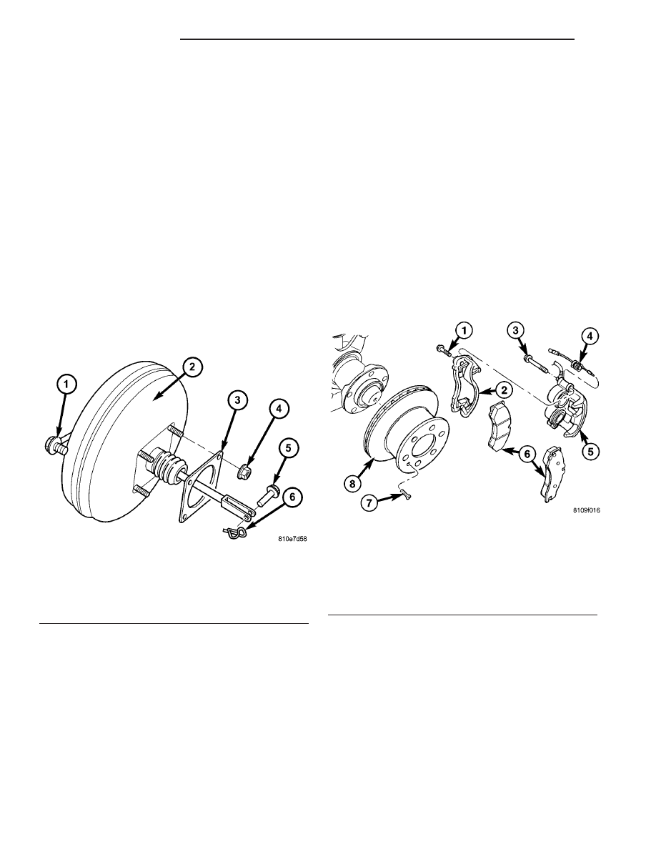
Fig. 23 POWER BRAKE BOOSTER

1 - VACUUM LINE & CHECK VALVE
2 - BRAKE BOOSTER
3 - GASKET
4 - MOUNTING NUTS (4)
5 - PUSH ROD PIN
6 - SECURING CLIP

Fig. 24 FRONT DISC BRAKE ROTOR

1 - CALIPER ADAPTER BOLT
2 - CALIPER ADAPTER
3 - GUIDE BOLT
4 - WEAR INDICATOR
5 - DISC BRAKE CALIPER
6 - DISC BRAKE PADS
7 - LOCKING BOLT
8 - DISC BRAKE ROTOR

5 - 20

BRAKES - BASE

VA

(10) loosen the park brake adjuster to allow clear-

ance for the rotor removal (Fig. 25).

(11) Remove the rear disc brake rotor.

REMOVAL - FRONT (DRW)

(1) Raise and support the vehicle.
(2) Remove the front wheels.
(3) Remove the front brake pads (Fig. 26).
(4) Remove the caliper adapter (Fig. 26).
(5) Remove the wheel flange ring (Fig. 26).
(6) Install two lug studs to secure the disc brake

rotor when the locking bolt is removed.

(7) Remove the locking bolt for the disc brake rotor

(Fig. 26).

(8) Remove the two lug nuts.
(9) Remove the disc brake rotor (Fig. 26).

REMOVAL - REAR (DRW)

(1) Raise and support the vehicle.
(2) Remove the rear wheels.
(3) Remove the rear disc brake pads (Fig. 27).
(4) Remove the disc brake caliper adapter (Fig.

27).

(5) Apply the parking brake.
(6) Install two lug studs to secure the disc brake

rotor when the locking bolt is removed.

(7) Remove the wheel flange ring (Fig. 27).
(8) Remove the locking bolt for the disc brake rotor

(Fig. 27).

(9) Remove the two lug nuts.
(10) Release the parking brake.
(11) loosen the park brake adjuster to allow clear-

ance for the rotor removal (Fig. 27).

(12) Remove the rear disc brake rotor.

Fig. 25 REAR DISC BRAKE ROTOR

1 - M8 BOLT
2 - CALIPER ADAPTER
3 - DISC BRAKE ROTOR
4 - LOCKING BOLT
5 - DISC BRAKE PADS
6 - RATTLE SPRING
7 - DISC BRAKE CALIPER
8 - GUIDE BOLT
9 - COVER
10 - WEAR INDICATOR

Fig. 26 FRONT DISC BRAKE ROTOR WITH DUAL

REAR WHEELS

1 - ADAPTER BOLT
2 - ADAPTER
3 - GUIDE PIN/BOLT
4 - WEAR INDICATOR WIRE
5 - DISC BRAKE CALIPER
6 - DISC BRAKE PADS
7 - WHEEL FLANGE RING MOUNTING BOLT
8 - WHEEL FLANGE RING
9 - LOCKING BOLT
10 - DISC BRAKE ROTOR

VA

BRAKES - BASE

5 - 21

INSTALLATION

INSTALLATION - FRONT (SRW)

(1) Install the disc brake rotor to the hub and

install two lug studs to hold rotor in place.

(2) Install the locking bolt for the rotor (Fig. 24).

Tighten to 23 N·m (204 in. lbs.).

(3) Install the disc brake caliper adapter (Fig. 24).

Tighten to 170 N·m (125 ft. lbs.) (Refer to 5 -
BRAKES/HYDRAULIC/MECHANICAL/DISC
BRAKE CALIPER ADAPTER - INSTALLATION).

(4) Install the brake pads (Refer to 5 - BRAKES/

HYDRAULIC/MECHANICAL/BRAKE PADS/SHOES
- INSTALLATION) (Fig. 24).

(5) Press and release the brake pedal several times

until pressure has built up.

(6) Check fluid in reservoir and correct if neces-

sary.

(7) Install the front wheels (Refer to 22 - TIRES/

WHEELS/WHEELS - INSTALLATION).

(8) Lower the vehicle.

INSTALLATION - REAR (SRW)

(1) Install the disc brake rotor to the hub and

install two lug studs to hold rotor in place (Fig. 25).

(2) Apply the parking brake.
(3) Install the locking bolt for the rotor (Fig. 25).

Tighten to 23 N·m (204 in. lbs.).

(4) Install the disc brake caliper adapter (Fig. 25).

Tighten to 90 N·m (66 ft. lbs.) (Refer to 5 - BRAKES/

HYDRAULIC/MECHANICAL/DISC

BRAKE

CALI-

PER ADAPTER - INSTALLATION).

(5) Install the brake pads (Refer to 5 - BRAKES/

HYDRAULIC/MECHANICAL/BRAKE PADS/SHOES
- INSTALLATION) (Fig. 25).

(6) Release the parking brake.
(7) Adjust

the

parking

brake

(Refer

to

5

-

BRAKES/PARKING

BRAKE/SHOES

-

ADJUST-

MENTS).

(8) Press and release the brake pedal several times

until pressure has built up.

(9) Check fluid in reservoir and correct if neces-

sary.

(10) Install the rear wheels.
(11) Lower the vehicle.

INSTALLATION - FRONT (DRW)

(1) Install the disc brake rotor to the hub and

install two lug studs to hold rotor in place.

(2) Install the locking bolt for the rotor (Fig. 26).

Tighten to 23 N·m (204 in. lbs.).

(3) Install the disc brake caliper adapter (Fig. 26).

Tighten to 170 N·m (125 ft. lbs.) (Refer to 5 -
BRAKES/HYDRAULIC/MECHANICAL/DISC
BRAKE CALIPER ADAPTER - INSTALLATION).

(4) Install the wheel flange ring. Tighten to 180

N·m (133 ft. lbs.)

(5) Install the brake pads (Refer to 5 - BRAKES/

HYDRAULIC/MECHANICAL/BRAKE PADS/SHOES
- INSTALLATION) (Fig. 26).

(6) Press and release the brake pedal several times

until pressure has built up.

(7) Check fluid in reservoir and correct if neces-

sary.

(8) Install the front wheels (Refer to 22 - TIRES/

WHEELS/WHEELS - INSTALLATION).

(9) Lower the vehicle.

INSTALLATION - REAR (DRW)

(1) Install the disc brake rotor to the hub and

install two lug studs to hold rotor in place (Fig. 27).

(2) Apply the parking brake.
(3) Install the locking bolt for the rotor (Fig. 27).

Tighten to 23 N·m (204 in. lbs.).

(4) Install the disc brake caliper adapter (Fig. 27).

Tighten to 170 N·m (125 ft. lbs.) (Refer to 5 -
BRAKES/HYDRAULIC/MECHANICAL/DISC
BRAKE CALIPER ADAPTER - INSTALLATION).

(5) Install the wheel flange ring (Fig. 27) Tighten

to 200 N·m (148 ft. lbs.).

(6) Install the brake pads (Refer to 5 - BRAKES/

HYDRAULIC/MECHANICAL/BRAKE PADS/SHOES
- INSTALLATION) (Fig. 27).

(7) Release the parking brake.
(8) Adjust

the

parking

brake

(Refer

to

5

-

BRAKES/PARKING

BRAKE/SHOES

-

ADJUST-

MENTS).

Fig. 27 REAR DISC BRAKE ROTOR WITH DUAL

REAR WHEELS

1 - ADAPTER BOLT
2 - ADAPTER
3 - GUIDE PIN/BOLT
4 - WEAR INDICATOR
5 - DISC BRAKE CALIPER
6 - RETAINING SPRING
7 - DISC BRAKE PADS
8 - WHEEL FLANGE RING MOUNITNG BOLT
9 - WHEEL FLANGE RING
10 - DISC BRAKE ROTOR

5 - 22

BRAKES - BASE

VA

(9) Press and release the brake pedal several times

until pressure has built up.

(10) Check fluid in reservoir and correct if neces-

sary.

(11) Install the rear wheels.
(12) Lower the vehicle.

SUPPORT PLATE

REMOVAL - REAR

(1) Raise and support the vehicle.
(2) Remove the disc brake caliper adapter (Refer to

5

-

BRAKES/HYDRAULIC/MECHANICAL/DISC

BRAKE CALIPER ADAPTER - REMOVAL).

(3) Remove the disc brake rotor (Refer to 5 -

BRAKES/HYDRAULIC/MECHANICAL/ROTORS

-

REMOVAL).

(4) Remove the rear park brake shoes (Refer to 5 -

BRAKES/PARKING BRAKE/SHOES - REMOVAL).

(5) Remove the park brake cable from he support

plate.

(6) Remove the rear axle bearing (Refer to 3 - DIF-

FERENTIAL

&

DRIVELINE/REAR

AXLE/AXLE

BEARINGS - REMOVAL).

(7) Remove brake support plate.

INSTALLATION - REAR

(1) Press the brake support plate with the axle

bearing onto the axle shaft (Refer to 3 - DIFFEREN-
TIAL & DRIVELINE/REAR AXLE/AXLE BEARINGS
- INSTALLATION).

(2) Install the park brake cable to the support

plate.

(3) Install the rear park brake shoes (Refer to 5 -

BRAKES/PARKING BRAKE/SHOES - INSTALLA-
TION).

(4) Install the disc brake rotor (Refer to 5 -

BRAKES/HYDRAULIC/MECHANICAL/ROTORS

-

INSTALLATION).

(5) Install the disc brake caliper adapter (Refer to

5

-

BRAKES/HYDRAULIC/MECHANICAL/DISC

BRAKE CALIPER ADAPTER - INSTALLATION).

(6) Adjust the rear park brake shoes (Refer to 5 -

BRAKES/PARKING

BRAKE/SHOES

-

ADJUST-

MENTS).

(7) Install the rear wheels (Refer to 22 - TIRES/

WHEELS/WHEELS - INSTALLATION).

PARKING BRAKE

SPECIFICATIONS

TORQUE CHART

TORQUE SPECIFICATIONS

DESCRIPTION

N·m

Ft. Lbs.

In. Lbs.

Pressure Transformer Unit

For Brake Cables To

Frame Crossmember

25

221

Hand Brake Lever To

Seat Frame

25

221

VA

BRAKES - BASE

5 - 23


Content   ..  22  23  24  25   ..