Dodge Sprinter. Manual - part 23


  Index      Dodge     Dodge Sprinter / Mercedes-Benz - service repair manual 2006 year


Search            


Content   ..  21  22  23  24   ..


Dodge Sprinter. Manual - part 23


(3) Check the brake system for any leaks.
(4) Reconnect the electrical connector to the brake

fluid level indicator (Fig. 14).

ALB LEVER

REMOVAL

(1) Raise and support the vehicle.
(2) Remove the retaining clip for the ALB lever

(Fig. 15).

(3) Remove the bolt for the lever at the axle (Fig.

15).

(4) Remove the lever.

INSTALLATION

(1) Install the lever to the vehicle.
(2) Install the lower mounting bolt to the axle (Fig.

15).

(3) Install the lever to the shock bolt and then

install the clip (Fig. 15).

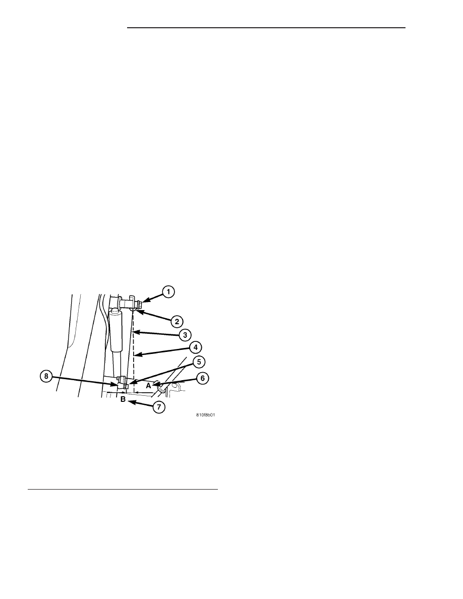
(4) Check the side deflection of the ALB lever with

a straight edge from Point-A to Point-B as the
graphic shows. Max deflection play of the actuator
rod should be no more than 15 mm (.60 in) (Fig. 15).

(5) Lower the vehicle.

ALB CONTROLLER

REMOVAL

(1) Install the brake pedal rod to hold the brake

pressure.

(2) Raise and support the vehicle.

(3) Remove the brake lines to the (automatic load-

dependant brake pressure control) ALB controller.

(4) Remove the adjusting nut and the spring from

the ALB controller.

(5) Remove the mounting bolts.
(6) Remove the ALB controller.

INSTALLATION

(1) Install the ALB controller to the vehicle.
(2) Install the mounting bolts for the controller.
(3) Install the brake lines. Tighten the lines to 16

N·m (142 in. lbs.)

(4) Install the adjusting rod, nut and spring to the

ALB controller.

(5) Lower the vehicle.
(6) Remove the brake pedal hold down rod.
(7) Fill and bleed the brake system (Refer to 5 -

BRAKES - STANDARD PROCEDURE).

(8) Raise the vehicle and adjust the ALB controller

(Refer to 5 - BRAKES/HYDRAULIC/MECHANICAL/
ALB CONTROLLER - ADJUSTMENTS).

(9) Lower the vehicle and test drive.

ADJUSTMENTS

ADJUSTMENT

(1) Clean any debris away from the test ports caps

at the ALB controller.

(2) Connect brake adapters special tool 9297 to the

test ports at the ALB controller.

(3) Install

a

Pressure

Gauge,

Special

Tool

C-4007-A, to the adapters.

(4) Tighten all tube nut fittings to 17 N·m (145 in.

lbs.) torque.

(5) Bleed any air out of the system. This includes

bleeding the air from the hose between the pressure
test fitting and pressure gauge, which is done at the
pressure gauge.

NOTE: Adjustment is determined for the automatic
load-dependent brake power control system accord-
ing to the ALB plate. This is housed in the stowage
compartment under the front passenger’s door
panel. The part number of the rear spring is
stamped into the spring eye. This must correspond
to the part number of the rear spring on the ALB
plate.

(6) To accurately adjust the rear axle load you

must first determine the rear axle load by weighing
the vehicle at a local scale.

(7) Install the brake pedal winch Special tool 9296

between the brake pedal and the driver seat and
slowly turn the dial until the specified inlet brake
pressure is indicated at the gauge.

Fig. 15 ALB LEVER DEFLECTION

1 - CLIP
2 - SPRING
3 - LEVER
4 - STRIAGHT EDGE
5 - NUT
6 - POINT -A
7 - POINT - B
8 - SUSPENSION POINT

5 - 16

BRAKES - BASE

VA

NOTE: The pressure gauge, connected at the ALB
controller must indicate the outlet pressure which
is assigned on the ALB plate to the rear axle load
determined.

NOTE: If the rear axle load determined is between
two figures indicated on the ALB plate, the outlet
pressure should be determined accordingly.

(8) If the pressure measured differs from the spec-

ification, adjust the ALB controller (Fig. 16).

(9) Loosen the brake pedal winch.
(10) Adjust the outlet pressure by turning the

adjusting nut (Fig. 16) To increase pressure -
tighten the adjusting nut. To reduce pressure -
loosen the adjusting nut.

(11) After adjustment reinstall the brake pedal

winch and recheck the pressures and readjust if
needed.

(12) Tighten the lock adjusting nut.

MASTER CYLINDER

DIAGNOSIS AND TESTING - MASTER CYLIN-
DER / POWER BOOSTER

(1) Start engine and check booster vacuum hose

connections. A hissing noise indicates vacuum leak.
Correct any vacuum leak before proceeding.

(2) Stop engine and shift transmission into Neu-

tral.

(3) Pump brake pedal until all vacuum reserve in

booster is depleted.

(4) Press and hold brake pedal under light foot

pressure. The pedal should hold firm, if the pedal
falls away master cylinder is faulty (internal leak-
age).

(5) Start engine and note pedal action. It should

fall away slightly under light foot pressure then hold

firm. If no pedal action is discernible, power booster,
vacuum supply, or vacuum check valve is faulty. Pro-
ceed to the POWER BOOSTER VACUUM TEST.

(6) If the POWER BOOSTER VACUUM TEST

passes, rebuild booster vacuum reserve as follows:
Release brake pedal. Increase engine speed to 1500
rpm, close the throttle and immediately turn off igni-
tion to stop engine.

(7) Wait a minimum of 90 seconds and try brake

action again. Booster should provide two or more vac-
uum assisted pedal applications. If vacuum assist is
not provided, booster is faulty.

POWER BOOSTER VACUUM TEST

(1) Connect vacuum gauge to booster check valve

with short length of hose and T-fitting (Fig. 17).

(2) Start and run engine at curb idle speed for one

minute.

(3) Observe the vacuum supply. If vacuum supply

is not adequate, repair vacuum supply.

(4) Clamp hose shut between vacuum source and

check valve.

(5) Stop engine and observe vacuum gauge.
(6) If vacuum drops more than one inch HG (33

millibars) within 15 seconds, booster diaphragm or
check valve is faulty.

POWER BOOSTER CHECK VALVE TEST

(1) Disconnect vacuum hose from check valve.
(2) Remove check valve and valve seal from

booster.

Fig. 16 ALB CONTROLLER ADJUSTER NUT

1 - ALB ADJUSTER NUT
2 - SPRING

Fig. 17 Typical Booster Vacuum Test Connections

1 - TEE FITTING
2 - SHORT CONNECTING HOSE
3 - CHECK VALVE
4 - CHECK VALVE HOSE
5 - CLAMP TOOL
6 - INTAKE MANIFOLD
7 - VACUUM GAUGE

VA

BRAKES - BASE

5 - 17

(3) Use a hand operated vacuum pump for test.
(4) Apply 15-20 inches vacuum at large end of

check valve (Fig. 18).

(5) Vacuum should hold steady. If gauge on pump

indicates vacuum loss, check valve is faulty and
should be replaced.

STANDARD PROCEDURE - MASTER CYLINDER
BLEEDING

A new master cylinder should be bled before instal-

lation on the vehicle. Required bleeding tools include
bleed tubes and a wood dowel to stroke the pistons.
Bleed tubes can be fabricated from brake line.

(1) Mount master cylinder in vise.
(2) Attach bleed tubes to cylinder outlet ports.

Then position each tube end into reservoir (Fig. 19).

(3) Fill reservoir with fresh brake fluid.
(4) Press cylinder pistons inward with wood dowel.

Then release pistons and allow them to return under
spring pressure. Continue bleeding operations until
air bubbles are no longer visible in fluid.

REMOVAL

(1) Using a suction gun remove as much brake

fluid from the reservoir as possible (Fig. 20).

(2) Remove the fluid reservoir (Fig. 20) or (Fig. 21)

(Refer to 5 - BRAKES/HYDRAULIC/MECHANICAL/
FLUID RESERVOIR - REMOVAL).

(3) Remove the brake lines Seal off the ends and

bore holes with plugs. (Fig. 20) or (Fig. 21)

(4) Remove the master cylinder mounting nuts

(Fig. 20) or (Fig. 21). Check brake booster for
damage due to leaking master cylinder. It is not
possible to repair the master cylinder.

Fig. 18 Vacuum Check Valve And Seal

1 - BOOSTER CHECK VALVE
2 - APPLY TEST VACUUM HERE
3 - VALVE SEAL

Fig. 19 Master Cylinder Bleeding–Typical

1 - BLEEDING TUBES
2 - RESERVOIR

Fig. 20 MASTER CYLINDER

1 - SUCTION GUN
2 - BRAKE FLUID CAP
3 - BRAKE FLUID LEVEL INDICATOR
4 - O-RING
5 - NUT
6 - BRAKE LINE
7 - MASTER CYLINDER
8 - FLUID RESERVOIR

5 - 18

BRAKES - BASE

VA

INSTALLATION

(1) Install the master cylinder to the brake booster

(Fig. 20). Tighten to 28 N·m (248 in. lbs.).

(2) Install the brake lines (Fig. 20). Tighten to 14

N·m (124 in. lbs.).

(3) Install the fluid reservoir (Fig. 20) (Refer to 5 -

BRAKES/HYDRAULIC/MECHANICAL/FLUID RES-
ERVOIR - INSTALLATION).

(4) Bleed the brake system.
(5) Check the brake system for any leaks.

PEDAL

REMOVAL

(1) Remove the master cylinder (Refer to 5 -

BRAKES/HYDRAULIC/MECHANICAL/MASTER
CYLINDER - REMOVAL).

(2) Remove the retainer and pin for the master

cylinder push rod (Fig. 22).

(3) Remove the retainer and pin for the brake

pedal pivot bolt (Fig. 22).

(4) Unhook the spring and remove the brake pedal

(Fig. 22).

(5) Disconnect the plug connector on the stop lamp

switch (Fig. 22).

(6) Remove the bolts and remove the pedal bearing

bracket (Fig. 22).

INSTALLATION

(1) Install the bolts for the pedal bearing bracket

(Fig. 22). Tighten to 23 N·m (204 in. lbs.)

(2) Reconnect the plug connector for the stop lamp

switch (Fig. 22).

(3) Install the brake pedal and hook the spring

(Fig. 22).

(4) Install the retainer and pin for the brake pedal

(Fig. 22).

(5) Install the retainer and pin for the master cyl-

inder push rod (Fig. 22).

(6) Install the master cylinder (Refer to 5 -

BRAKES/HYDRAULIC/MECHANICAL/MASTER
CYLINDER - INSTALLATION).

POWER BRAKE BOOSTER

DESCRIPTION

All models use a tandem diaphragm, power brake

booster.

NOTE: The power brake booster is not a repairable
component. The booster must be replaced as an
assembly if diagnosis indicates a malfunction has
occurred.

OPERATION

The booster unit consists of a single housing

divided into two by a tandem diaphragm. The outer

Fig. 21 MASTER CYLINDER (DRW)

1 - POWER BRAKE BOOSTER
2 - RESERVOIR
3 - BRAKE LINES
4 - PRESSURE PORTS
5 - MASTER CYLINDER

Fig. 22 BRAKE PEDAL

1 - MOUNTING BOLT
2 - PEDAL BEARING BRACKET
3 - STOP LAMP SWITCH
4 - CLIP
5 - PIVOT BOLT
6 - RETURN SPRING
7 - PEDAL
8 - PUSH ROD BOLT
9 - PUSH ROD
10 - CLIP
11 - BOLT
12 - WASHER

VA

BRAKES - BASE

5 - 19


Content   ..  21  22  23  24   ..