Dodge Ram Truck 1500-2500-3500. Manual - part 878
P0344-CAMSHAFT POSITION SENSOR INTERMITTENT (CONTINUED)
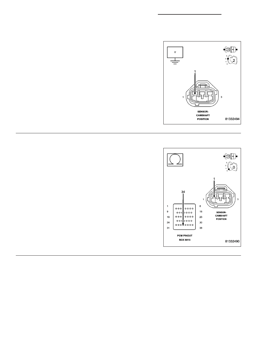
8.
(K44) CMP SIGNAL CIRCUIT SHORTED TO BATTERY VOLTAGE
Turn the ignition off.
Disconnect the CMP Sensor connector.
Disconnect the C2 PCM harness connector.
Ignition on, engine not running.
Measure the voltage on the (K44) CMP Signal circuit.
Wiggle the related wire harness while taking this measurement.
Does the voltage ever increase above 0 volts?
Yes
>> Repair the short to battery voltage in the (K44) CMP Sig-
nal circuit.
Perform the POWERTRAIN VERIFICATION TEST. (Refer
to 9 - ENGINE - STANDARD PROCEDURE)
No
>> Go To 9
9.
(K44) CMP SIGNAL CIRCUIT OPEN
Turn the ignition off.
CAUTION: Do not probe the PCM harness connectors. Probing
the PCM harness connectors will damage the PCM terminals
resulting in poor terminal to pin connection. Install Miller Special
Tool #8815 to perform diagnosis.
Measure the resistance in the (K44) CMP Signal circuit from the CMP
harness connector to the appropriate terminal of special tool #8815.
Wiggle the related wire harness while taking this measurement.
Is the resistance below 5.0 ohms?
Yes
>> Go To 10
No
>> Repair the excessive resistance in the (K44) CMP Signal
circuit.
Perform the POWERTRAIN VERIFICATION TEST. (Refer
to 9 - ENGINE - STANDARD PROCEDURE)
9 - 434
ENGINE - ELECTRICAL DIAGNOSTICS - 3.7L/4.7L/5.7L
DR/DH