Dodge Neon / Neon SRT-4. Manual - part 443


  Index      Dodge     Dodge Neon / Neon SRT-4 - service repair manual 2005 year


Search            


Content   ..  441  442  443  444   ..


Dodge Neon / Neon SRT-4. Manual - part 443


PCV VALVE

DESCRIPTION

Is a plastic valve in the engine valve cover (Fig. 6).

OPERATION

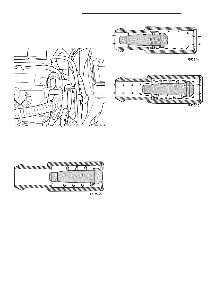
When the engine is not operating or during an

engine backfire, the spring forces the plunger back
against the seat. This prevents vapors from flowing
through the valve (Fig. 7).

When the engine is at idle or cruising, high mani-

fold vacuum is present. At these times manifold vac-
uum is able to completely compress the spring and
pull the plunger to the top of the valve (Fig. 8). In
this position there is minimal vapor flow through the
valve.

During periods of moderate intake manifold vac-

uum the plunger is only pulled part way back from
the inlet. This results in maximum vapor flow
through the valve (Fig. 9).

DIAGNOSIS AND TESTING - PCV SYSTEM

WARNING:

APPLY

PARKING

BRAKE

AND/OR

BLOCK WHEELS BEFORE PERFORMING ANY TEST
OR ADJUSTMENT WITH THE ENGINE OPERATING.

(1) With engine idling, remove the hose from the

PCV valve. If the valve is not plugged, a hissing
noise will be heard as air passes through the valve. A
strong vacuum should also be felt when a finger is
placed over the valve inlet.

(2) Install

hose

on

PCV

valve.

Remove

the

make-up air hose from the air plenum at the rear of
the engine. Hold a piece of stiff paper (parts tag)
loosely over the end of the make-up air hose.

(3) After allowing approximately one minute for

crankcase pressure to reduce, the paper should draw
up against the hose with noticeable force. If the
engine does not draw the paper against the grommet
after installing a new valve, replace the PCV valve
hose.

(4) Turn the engine off. Remove the PCV valve

from intake manifold. The valve should rattle when
shaken.

(5) Replace the PCV valve and retest the system if

it does not operate as described in the preceding
tests. Do not attempt to clean the old PCV valve.
If the valve rattles, apply a light coating of Loctite

t

Pipe Sealant With Teflon to the threads. Thread the
PCV valve into the manifold plenum and tighten to 7
N·m (60 in. lbs.) torque.

Fig. 6 PCV System - 2.0L

Fig. 7 Engine Off or Engine Backfire No Vapor Flow

Fig. 8 High Intake Manifold Vacuum Minimal Vapor

Flow

Fig. 9 Moderate Intake Manifold Vacuum Maximum

Vapor Flow

25 - 16

EVAPORATIVE EMISSIONS

PL/SRT-4

REMOVAL - 1.6L

(1) Remove the bolt for the PCV valve (Fig. 10).

(2) Remove the hose.
(3) Remove the PCV (Fig. 11).

INSTALLATION - 1.6L

(1) Lubericate the O-ring on the valve (Fig. 11).
(2) Install the PCV Valve (Fig. 10) and tighen the

bolt to 8.1 N·m (72 in. lbs.).

(3) Install the hose.

VAPOR CANISTER

DESCRIPTION

The vacuum and vapor tubes connect to the top of

the canister (Fig. 12).

OPERATION

All vehicles use a maintenance free, evaporative

(EVAP) canister. Fuel tank vapors vent into the can-
ister. The canister temporarily holds the fuel vapors
until intake manifold vacuum draws them into the
combustion chamber. The Powertrain Control Module
(PCM) purges the canister through the proportional
purge solenoid. The PCM purges the canister at pre-
determined intervals and engine conditions.

Purge Free Cells

Purge-free memory cells are used to identify the

fuel vapor content of the evaporative canister. Since
the evaporative canister is not purged 100% of the
time, the PCM stores information about the evapora-
tive canister’s vapor content in a memory cell.

The purge-free cells are constructed similar to cer-

tain purge-normal cells. The purge-free cells can be
monitored by the DRB III

t Scan Tool. The only dif-

ference between the purge-free cells and normal
adaptive cells is that in purge-free, the purge is com-
pletely turned off. This gives the PCM the ability to
compare purge and purge-free operation.

Fig. 10 PCV VALVE LOCATION - 1.6L

Fig. 11 PCV VALVE - 1.6L

Fig. 12 EVAP Canister

PL/SRT-4

EVAPORATIVE EMISSIONS

25 - 17

PCV VALVE (Continued)

REMOVAL

(1) Disconnect the negative battery cable.
(2) Raise vehicle and support.
(3) Disconnect the hoses from the EVAP canister

(Fig. 13).

(4) Remove 1 nut from the bracket of the EVAP

canister (Fig. 14).

(5) Remove EVAP canister from bracket.

INSTALLATION

(1) Install EVAP canister to Bracket (Fig. 14).

(2) Install 2 nuts to EVAP canister and bracket

and tighten nuts to 6.7 N·m (60 in. lbs.).

(3) Connect hoses.
(4) Install EVAP canister and bracket to vehicle

and tighten nut 22.4 N·m (250 in. lbs.).

(5) Lower vehicle.
(6) Connect negative battery cable.

Fig. 13 EVAP Canister

Fig. 14 EVAP

25 - 18

EVAPORATIVE EMISSIONS

PL/SRT-4

VAPOR CANISTER (Continued)

ON-BOARD DIAGNOSTICS

TABLE OF CONTENTS

page

page

TASK MANAGER

DESCRIPTION

. . . . . . . . . . . . . . . . . . . . . . . . . 19

OPERATION

. . . . . . . . . . . . . . . . . . . . . . . . . . . 19

TASK MANAGER

DESCRIPTION

The PCM is responsible for efficiently coordinating

the operation of all the emissions-related compo-
nents. The PCM is also responsible for determining if
the diagnostic systems are operating properly. The
software designed to carry out these responsibilities
is call the “Task Manager”.

OPERATION

The Task Manager determines when tests happen

and when functions occur. Many of the diagnostic
steps required by OBD II must be performed under
specific operating conditions. The Task Manager soft-
ware organizes and prioritizes the diagnostic proce-
dures. The job of the Task Manager is to determine if
conditions are appropriate for tests to be run, moni-
tor the parameters for a trip for each test, and record
the results of the test. Following are the responsibil-
ities of the Task Manager software:

• Test Sequence

• MIL Illumination

• Diagnostic Trouble Codes (DTCs)

• Trip Indicator

• Freeze Frame Data Storage

• Similar Conditions Window

Test Sequence

In many instances, emissions systems must fail

diagnostic tests more than once before the PCM illu-
minates the MIL. These tests are known as ’two trip
monitors.’ Other tests that turn the MIL lamp on
after a single failure are known as ’one trip moni-
tors.’ A trip is defined as ’start the vehicle and oper-
ate it to meet the criteria necessary to run the given
monitor.’

Many of the diagnostic tests must be performed

under certain operating conditions. However, there
are times when tests cannot be run because another
test is in progress (conflict), another test has failed
(pending) or the Task Manager has set a fault that
may cause a failure of the test (suspend).

• Pending

Under some situations the Task Manager will not

run a monitor if the MIL is illuminated and a fault is
stored from another monitor. In these situations, the
Task Manager postpones monitors pending resolu-
tion of the original fault. The Task Manager does not
run the test until the problem is remedied.
For example, when the MIL is illuminated for an
Oxygen Sensor fault, the Task Manager does not run
the Catalyst Monitor until the Oxygen Sensor fault is
remedied. Since the Catalyst Monitor is based on sig-
nals from the Oxygen Sensor, running the test would
produce inaccurate results.

• Conflict

There are situations when the Task Manager does
not run a test if another monitor is in progress. In
these situations, the effects of another monitor run-
ning could result in an erroneous failure. If this con-
flict 
is present, the monitor is not run until the
conflicting condition passes. Most likely the monitor
will run later after the conflicting monitor has
passed.
For example, if the Fuel System Monitor is in
progress, the Task Manager does not run the catalyst
Monitor. Since both tests monitor changes in air/fuel
ratio and adaptive fuel compensation, the monitors
will conflict with each other.

• Suspend

Occasionally the Task Manager may not allow a two
trip fault to mature. The Task Manager will sus-
pend 
the maturing of a fault if a condition exists
that may induce an erroneous failure. This prevents
illuminating the MIL for the wrong fault and allows
more precise diagnosis.
For example, if the PCM is storing a one trip fault
for the Oxygen Sensor and the catalyst monitor, the
Task Manager may still run the catalyst Monitor but
will suspend the results until the Oxygen Sensor
Monitor either passes or fails. At that point the Task
Manager can determine if the catalyst system is
actually failing or if an Oxygen Sensor is failing.

MIL Illumination

The PCM Task Manager carries out the illumina-

tion of the MIL. The Task Manager triggers MIL illu-
mination upon test failure, depending on monitor
failure criteria.

PL/SRT-4

ON-BOARD DIAGNOSTICS

25 - 19


Content   ..  441  442  443  444   ..