Dodge Neon / Neon SRT-4. Manual - part 442


  Index      Dodge     Dodge Neon / Neon SRT-4 - service repair manual 2005 year


Search            


Content   ..  440  441  442  443   ..


Dodge Neon / Neon SRT-4. Manual - part 442


EVAP/PURGE SOLENOID

DESCRIPTION (Fig. 2)

OPERATION

All vehicles use a proportional purge solenoid. The

solenoid regulates the rate of vapor flow from the
EVAP canister to the throttle body. The PCM oper-
ates the solenoid.

During the cold start warm-up period and the hot

start time delay, the PCM does not energize the sole-
noid. When de-energized, no vapors are purged.

The proportional purge solenoid operates at a fre-

quency of 200 hz and is controlled by an engine con-
troller circuit that senses the current being applied
to the proportional purge solenoid (Fig. 2) and then
adjusts that current to achieve the desired purge
flow. The proportional purge solenoid controls the

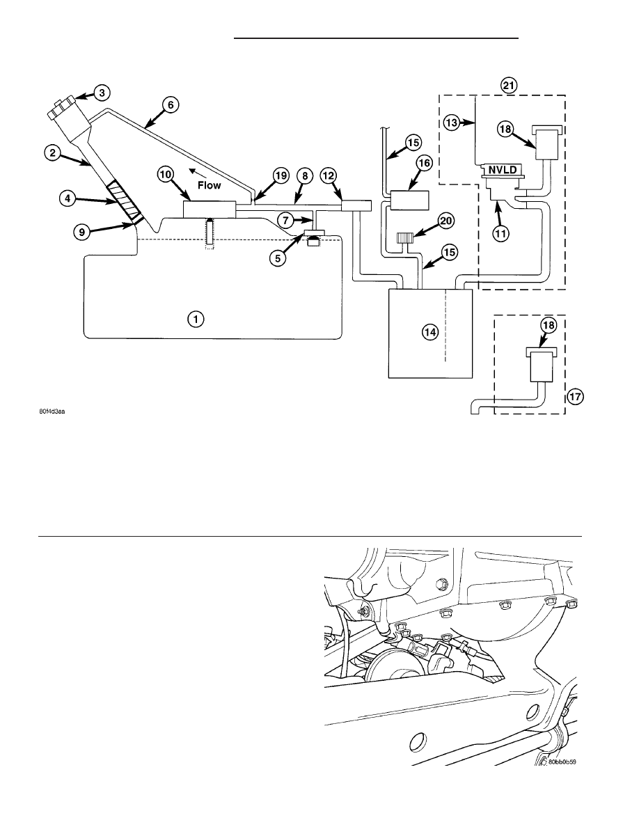
Fig. 1 ORVR System Schematic (PZEV)

1 - FUEL TANK (PLASTIC)

11 - NATURAL VACUUM LEAD DETECTION (NVLD)

2 - FUEL FILLER TUBE

12 - LIQUID SEPARATOR (IF EQUIPPED)

3 - FUEL CAP (PRESSURE/RELIEF)

13 - ENGINE WIRING HARNESS TO NVLD

4 - FILL TUBE TO FUEL TANK CONNECTOR (ELASTOMERIC)

14 - VAPOR CANISTER

5 - TANK VENT/ROLLOVER VALVE(S)

15 - PURGE LINE

6 - VAPOR RECIRCULATION LINE

16 - PURGE DEVICE

7 - TANK VAPOR LINE

17 - WITHOUT NVLD

8 - VAPOR LINE TO CANISTER

18 - BREATHER ELEMENT

9 - CHECK VALVE (N/C)

19 - FLOW CONTROL ORIFICE

10 - CONTROL VALVE

20 - SERVICE PORT
21 - WITH NVLD

Fig. 2 Proportional Purge Solenoid

25 - 12

EVAPORATIVE EMISSIONS

PL/SRT-4

EVAPORATIVE EMISSIONS (Continued)

purge rate of fuel vapors from the vapor canister and
fuel tank to the engine intake manifold.

REMOVAL

The solenoid attaches to a bracket near the steer-

ing gear (Fig. 3). The solenoid will not operate unless
it is installed correctly.

(1) Raise vehicle and support.
(2) Disconnect electrical connector from solenoid.
(3) Disconnect vacuum tubes from solenoid.
(4) Remove solenoid from bracket.

INSTALLATION

The solenoid attaches to a bracket near the steer-

ing gear (Fig. 3). The solenoid will not operate unless
it is installed correctly.

The top of the solenoid has TOP printed on it. The

solenoid will not operate unless it is installed cor-
rectly.

(1) Install solenoid on bracket.
(2) Connect vacuum tube to solenoid.
(3) Connect electrical connector to solenoid.
(4) Lower vehicle.

FUEL FILLER CAP

DESCRIPTION

The plastic fuel fill cap is threaded/quarter turn

onto the end of the fuel filler tube. It’s purpose is to
retain vapors and fuel in the fuel tank.

OPERATION

The fuel filler cap incorporates a two-way relief

valve that is closed to atmosphere during normal
operating conditions. The relief valve is calibrated to
open when a pressure of 17 kPa (2.5 psi) or vacuum
of 2 kPa (0.6 in. Hg) occurs in the fuel tank. When
the pressure or vacuum is relieved, the valve returns
to the normally closed position.

CAUTION: Remove the fuel filler cap to release fuel
tank pressure before disconnecting any fuel system
component.

LEAK DETECTION PUMP

REMOVAL

(1) Raise and support vehicle on a hoist.
(2) Push locking tab on electrical connector to

unlock and remove connector.

(3) loosen the sway bar bracket to remove the

pump bracket.

(4) Remove pump and bracket as an assembly.
(5) Disconnect lines from NVLD.
(6) Remove filter.
(7) Remove from bracket.

INSTALLATION

(1) Install pump to bracket and tighten bolts to 1.2

N·m (10.6 in. lbs.).

(2) Install filter and tighten to 2.8 N·m (25 in.

lbs.).

NOTE: The LDP bracket must be between the rail
and sway bar bracket.

(3) Install pump and bracket assembly to body and

tighten front bolt to 11.7 N·m (105 in. lbs.).

(4) Install sway bar bracket bolt and tighten bolts

to 33.8 N·m (25 ft. lbs.).

(5) Before installing hoses to LDP, make sure

they are not cracked or split. If a hose leaks, it
will cause the Check Engine Lamp to illumi-
nate. 
Connect lines to the LDP.

(6) Install electrical connector to pump and push

locking tab to lock.

(7) Lower vehicle
(8) Use the DRB III

t scan tool, verify proper oper-

ation of LDP.

Fig. 3 Proportional Purge Solenoid Valve

PL/SRT-4

EVAPORATIVE EMISSIONS

25 - 13

EVAP/PURGE SOLENOID (Continued)

ON-BOARD REFUELING
VAPOR RECOVERY

DESCRIPTION

Onboard Refueling Vapor Recovery (ORVR) System

Schematic and components (Fig. 4).

OPERATION

The emission control principle used in the ORVR

system is that the fuel flowing into the filler tube
(appx. 1” I.D.) creates an aspiration effect which
draws air into the fill tube (Fig. 5). During refueling,
the fuel tank is vented to the vapor canister to cap-
ture escaping vapors. With air flowing into the filler
tube, there are no fuel vapors escaping to the atmo-
sphere. Once the refueling vapors are captured by

the canister, the vehicle’s computer controlled purge
system draws vapor out of the canister for the engine
to burn. The vapors flow is metered by the purge
solenoid so that there is no or minimal impact on
driveability or tailpipe emissions.

As fuel starts to flow through the fill tube, it opens

the normally closed check valve and enters the fuel
tank. Vapor or air is expelled from the tank through
the control valve to the vapor canister. Vapor is
absorbed in the canister until vapor flow in the lines
stops, either following shut-off or by having the fuel
level in the tank rise high enough to close the control
valve. The control valve(Refer to 14 - FUEL SYS-
TEM/FUEL DELIVERY/FUEL TANK - OPERATION)
contains a float that rises to seal the large diameter
vent path to the canister. At this point in the fueling
of the vehicle, the tank pressure increases, the check

Fig. 4 ORVR System Schematic

1 - FUEL TANK (PLASTIC)

11 - NATURAL VACUUM LEAD DETECTION (NVLD)

2 - FUEL FILLER TUBE

12 - LIQUID SEPARATOR (IF EQUIPPED)

3 - FUEL CAP (PRESSURE/RELIEF)

13 - ENGINE WIRING HARNESS TO NVLD

4 - FILL TUBE TO FUEL TANK CONNECTOR (ELASTOMERIC)

14 - VAPOR CANISTER

5 - TANK VENT/ROLLOVER VALVE(S)

15 - PURGE LINE

6 - VAPOR RECIRCULATION LINE

16 - PURGE DEVICE

7 - TANK VAPOR LINE

17 - WITHOUT NVLD

8 - VAPOR LINE TO CANISTER

18 - BREATHER ELEMENT

9 - CHECK VALVE (N/C)

19 - FLOW CONTROL ORIFICE

10 - CONTROL VALVE

20 - SERVICE PORT
21 - WITH NVLD

25 - 14

EVAPORATIVE EMISSIONS

PL/SRT-4

valve closes (preventing tank fuel from spitting back
at the operator), and fuel then rises up the filler tube
to shut-off the dispensing nozzle.

If the engine is shut-off while the On-Board diag-

nostics test is running, low level tank pressure can
be trapped in the fuel tank and fuel can not be added
to the tank until the pressure is relieved. This is due
to the leak detection pump closing the vapor outlet
from the top of the tank and the one-way check valve

not allowing the tank to vent through the fill tube to
atmosphere. Therefore, when fuel is added, it will
back-up in the fill tube and shut off the dispensing
nozzle. The pressure can be eliminated in two ways:
1. Vehicle purge must be activated and for a long
enough period to eliminate the pressure. 2. Removing
the fuel cap and allowing enough time for the system
to vent thru the recirulation tube.

Fig. 5 ORVR System Schematic

1 - FUEL TANK (PLASTIC)

11 - NATURAL VACUUM LEAD DETECTION (NVLD)

2 - FUEL FILLER TUBE

12 - LIQUID SEPARATOR (IF EQUIPPED)

3 - FUEL CAP (PRESSURE/RELIEF)

13 - ENGINE WIRING HARNESS TO NVLD

4 - FILL TUBE TO FUEL TANK CONNECTOR (ELASTOMERIC)

14 - VAPOR CANISTER

5 - TANK VENT/ROLLOVER VALVE(S)

15 - PURGE LINE

6 - VAPOR RECIRCULATION LINE

16 - PURGE DEVICE

7 - TANK VAPOR LINE

17 - WITHOUT NVLD

8 - VAPOR LINE TO CANISTER

18 - BREATHER ELEMENT

9 - CHECK VALVE (N/C)

19 - FLOW CONTROL ORIFICE

10 - CONTROL VALVE

20 - SERVICE PORT
21 - WITH NVLD

PL/SRT-4

EVAPORATIVE EMISSIONS

25 - 15

ON-BOARD REFUELING VAPOR RECOVERY (Continued)


Content   ..  440  441  442  443   ..