Dodge Neon / Neon SRT-4. Manual - part 437


  Index      Dodge     Dodge Neon / Neon SRT-4 - service repair manual 2005 year


Search            


Content   ..  435  436  437  438   ..


Dodge Neon / Neon SRT-4. Manual - part 437


2.4L AND RHD MODELS

(1) Recover the refrigerant from the refrigerant

system (Refer to 24 - HEATING & AIR CONDITION-
ING - STANDARD PROCEDURE - REFRIGERANT
SYSTEM RECOVERY).

(2) Disconnect and isolate the negative battery

cable.

(3) Remove the bolt that secures the liquid line fit-

ting to the condenser outlet port (upper fitting) (Fig.
21).

(4) Disconnect the liquid line fitting from the con-

denser outlet port and remove and discard the O-ring
seal.

(5) Install plugs in, or tape over the opened liquid

line fitting and the condenser outlet port.

(6) If equipped, relocate the vehicle speed control

servo as necessary to access the receiver/drier.

(7) Remove the two bolts that secure the liquid

lines to the receiver/drier (Fig. 23).

(8) Remove the liquid lines from the receiver/drier

and remove and discard the O-ring seals.

(9) Install plugs in, or tape over the opened liquid

line fittings and receiver/drier ports.

(10) Remove the front section of the liquid line

from the engine compartment.

(11) Disconnect the front suction line fitting from

the mid-line connector block of the rear suction and
liquid line assembly and remove and discard the
O-ring seal.

(12) Install plugs in, or tape over the opened front

suction line fitting and the mid-line connector block
of the suction and liquid line assembly.

(13) Remove the bolt that secures the rear suction

and liquid line assembly to the A/C expansion valve.

(14) Disconnect the rear suction and liquid line

assembly from the A/C expansion valve

(15) Remove the gasket from the A/C expansion

valve and discard.

(16) Install plugs in, or tape over the opened rear

suction and liquid line fittings and both expansion
valve ports.

(17) Disengage the rear suction and liquid line

assembly from the retaining clips as required and
remove the rear suction and liquid line assembly
from the engine compartment.

INSTALLATION

2.0L LHD MODELS

(1) Position the liquid line into the engine com-

partment.

(2) Remove the tape or plugs from the suction and

liquid line fittings and the evaporator tube tapping
plate port.

(3) Install a new gasket onto the evaporator tube

tapping plate.

(4) Connect the liquid and suction line fittings to

the evaporator tube tapping plate.

(5) Install the two bolts that secure the liquid and

suction line fittings to the evaporator tube tapping
plate plate. Tighten the bolts to 10 N·m (88 in. lbs.).

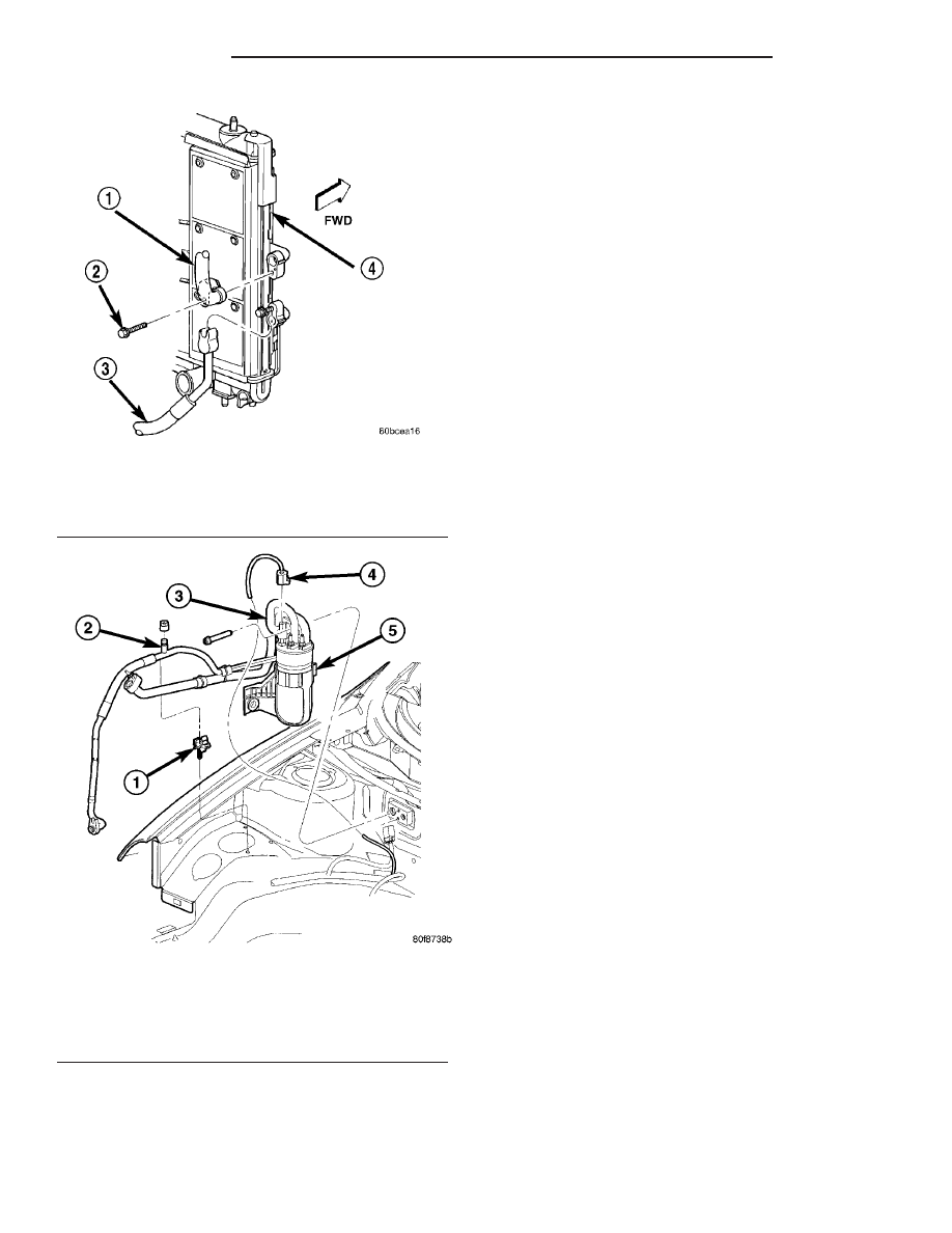
Fig. 21 Refrigerant Lines - A/C Condenser

1 - LIQUID LINE
2 - BOLT (2)
3 - DISCHARGE LINE
4 - A/C CONDENSER

Fig. 22 Liquid Line - 2.0L LHD Models

1 - LIQUID LINE MOUNTING CLIP
2 - A/C CHARGE PORT
3 - A/C LOW PRESSURE SWITCH
4 - A/C LOW PRESSURE SWITCH CONNECTOR
5 - ACCUMULATOR

24 - 56

PLUMBING

PL/SRT-4

LIQUID LINE (Continued)

(6) Install the accumulator (Refer to 24 - HEAT-

ING & AIR CONDITIONING/PLUMBING/ACCU-
MULATOR - INSTALLATION).

(7) Remove the tape or plugs from the liquid line

fitting and the condenser outlet port.

(8) Lubricate a new rubber O-ring seal with clean

refrigerant oil and install it on the liquid line fitting.
Use only the specified O-rings as they are made of a
special material for the R-134a system. Use only
refrigerant oil of the type recommended for the com-
pressor in the vehicle.

(9) Install the liquid line fitting to the condenser

outlet port.

(10) Install the bolt that secures the liquid line fit-

ting to the condenser outlet port. Tighten the bolt to
12 N·m (108 in. lbs.).

(11) Evacuate the refrigerant system (Refer to 24 -

HEATING & AIR CONDITIONING/PLUMBING -
STANDARD PROCEDURE - REFRIGERANT SYS-
TEM EVACUATE)

(12) Recharge the A/C system (Refer to 24 - HEAT-

ING & AIR CONDITIONING - STANDARD PROCE-
DURE - REFRIGERANT SYSTEM CHARGE).

2.4L AND RHD MODELS

(1) Position the rear suction and liquid line assem-

bly into the engine compartment.

(2) Engage the rear suction and liquid line assem-

bly to the retaining clips as required.

(3) Remove the tape or plugs from the liquid and

suction line fittings and both ports on the front of the
A/C expansion valve.

(4) Install a new gasket onto the A/C expansion

valve.

(5) Connect the liquid and suction line fitting to

the A/C expansion valve.

(6) Install the bolt that secures the suction and

liquid line fitting to the A/C expansion valve. Tighten
the bolt to 20 N·m (15 ft. lbs.).

(7) Remove the tape or plugs from the front suc-

tion line fitting and the mid-line connector block of
the suction and liquid line assembly.

(8) Lubricate a new rubber O-ring seal with clean

refrigerant oil and install it on the suction line fit-
ting. Use only the specified O-rings as they are made
of a special material for the R-134a system. Use only
refrigerant oil of the type recommended for the com-
pressor in the vehicle.

(9) Connect the front suction line fitting to the

mid-line connector block.

(10) Install the nut that secures the front suction

line fitting to the mid-line connector block. Tighten
the nut to 4.5 N·m (40 in. lbs.).

(11) Position the front section of the liquid line

into the engine compartment.

(12) Remove the tape or plugs from the opened liq-

uid line fittings and receiver/drier ports.

(13) Lubricate new rubber O-ring seals with clean

refrigerant oil and install them on the liquid line fit-
tings. Use only the specified O-rings as they are
made of a special material for the R-134a system.
Use only refrigerant oil of the type recommended for
the compressor in the vehicle.

(14) Reconnect the liquid line fittings to the receiv-

er/drier.

(15) Install the bolts that secure the liquid line fit-

tings to the receiver/drier. Tighten the bolts to 2.3
N·m (20 in. lbs.).

(16) If equipped, reinstall the vehicle speed control

servo.

(17) Remove the tape or plug from the condenser

outlet port and the liquid line fitting.

(18) Lubricate a new rubber O-ring seal with clean

refrigerant oil and install it on the liquid line fitting.
Use only the specified O-rings as they are made of a
special material for the R-134a system. Use only
refrigerant oil of the type recommended for the com-
pressor in the vehicle.

(19) Reconnect the liquid line fitting to the con-

denser outlet port.

Fig. 23 Liquid Line - 2.4L LHD Shown, RHD Typical

1 - RECEIVER/DRIER
2 - SUCTION AND LIQUID LINE ASSEMBLY (REAR)
3 - BOLT
4 - RECEIVER/DRIER MOUNTING GROMMET
5 - A/C LOW PRESSURE SWITCH
6 - CONDENSATE DRAIN TUBE
7 - A/C EXPANSION VALVE
8 - BOLT
9 - LIQUID LINE (FRONT)
10 - SUCTION LINE (FRONT)

PL/SRT-4

PLUMBING

24 - 57

LIQUID LINE (Continued)

(20) Install and tighten the bolt that secures the

liquid line fitting to the condenser outlet port.
Tighten the bolt to 12 N·m (108 in. lbs.).

(21) Evacuate the refrigerant system (Refer to 24 -

HEATING & AIR CONDITIONING - STANDARD
PROCEDURE - REFRIGERANT SYSTEM EVACU-
ATE).

(22) Charge the refrigerant system (Refer to 24 -

HEATING & AIR CONDITIONING - STANDARD
PROCEDURE

-

REFRIGERANT

SYSTEM

CHARGE).

RECEIVER / DRIER - 2.4L AND
RHD MODELS

DESCRIPTION

A receiver/drier (Fig. 24) is used on 2.4L and RHD

models. The receiver/drier is mounted on the right
side of the engine compartment and is located
between the A/C condenser outlet and A/C evaporator
inlet.

The receiver/drier cannot be repaired and, if faulty

or damaged, or if the refrigerant system has been
contaminated or left open to the atmosphere for an
indeterminable period of time, or if the A/C compres-
sor has failed, the receiver/drier must be replaced.

OPERATION

The receiver/drier performs a filtering action to

prevent foreign material in the refrigerant from con-
taminating the A/C expansion valve. Refrigerant
enters the receiver/drier as a high-pressure, low tem-
perature liquid. Desiccant inside the receiver/drier
absorbs any moisture which may have entered and
become trapped within the refrigerant system. In
addition, during periods of high demand operation of
the A/C system, the receiver/drier acts as a reservoir
to store surplus refrigerant.

The receiver/drier cannot be repaired. If the receiv-

er/drier is faulty or damaged, or if the refrigerant
system has been contaminated or left open to the
atmosphere for an indeterminable period or if the
A/C compressor has failed, it must be replaced.

REMOVAL

WARNING: Review the warnings and cautions in the
front of this section before performing the following
operation (Refer to 24 - HEATING & AIR CONDI-
TIONING/PLUMBING - WARNING - A/C SYSTEM) and
(Refer to 24 - HEATING & AIR CONDITIONING/
PLUMBING - CAUTION - A/C SYSTEM).

(1) Recover the refrigerant from the refrigerant

system (Refer to 24 - HEATING & AIR CONDITION-

ING/PLUMBING

-

STANDARD

PROCEDURE

-

REFRIGERANT SYSTEM RECOVERY).

(2) Remove the two bolts that secure the liquid

lines to the receiver/drier (Fig. 25).

(3) Remove the liquid lines from the receiver/drier

and remove and discard the O-ring seals.

(4) Install plugs in, or tape over the opened liquid

line fittings and receiver/drier ports.

(5) Remove the receiver/drier from mounting grom-

met and the engine compartment.

INSTALLATION

NOTE: If the receiver/drier is being replaced, add 30
milliliters (1 fluid ounce) of refrigerant oil to the
refrigerant system. Use only refrigerant oil of the
type recommended for the A/C compressor in the
vehicle.

(1) Position the receiver/drier into the engine com-

partment and onto the mounting grommet.

(2) Remove the tape or plugs from the opened liq-

uid line fittings and receiver/drier ports.

Fig. 24 Receiver/Drier with Refrigerant Lines -

Typical

1 - CONDENSER FITTING
2 - LIQUID LINE
3 - RECEIVER/DRIER
4 - HIGH SIDE SERVICE PORT
5 - MOUNTING BRACKET
6 - INSULATOR (2)
7 - RETAINER BRACKET
8 - MOUNTING FLANGE
9 - LOW SIDE SERVICE PORT
10 - SUCTION LINE
11 - SUCTION LINE FITTING

24 - 58

PLUMBING

PL/SRT-4

LIQUID LINE (Continued)

(3) Lubricate new rubber O-ring seals with clean

refrigerant oil and install them on the liquid line fit-
tings. Use only the specified O-rings as they are
made of a special material for the R-134a system.
Use only refrigerant oil of the type recommended for
the compressor in the vehicle.

(4) Connect the liquid line fittings to the receiver/

drier.

(5) Install the bolts that secure the liquid line fit-

tings to the receiver/drier. Tighten the bolts to 2.3
N·m (20 in. lbs.).

(6) Evacuate the refrigerant system (Refer to 24 -

HEATING & AIR CONDITIONING - STANDARD
PROCEDURE - REFRIGERANT SYSTEM EVACU-
ATE).

(7) Charge the refrigerant system (Refer to 24 -

HEATING & AIR CONDITIONING - STANDARD
PROCEDURE

-

REFRIGERANT

SYSTEM

CHARGE).

REFRIGERANT

DESCRIPTION

The refrigerant used in this air conditioning sys-

tem is a HydroFluoroCarbon (HFC), type R-134a.
Unlike R-12, which is a ChloroFluoroCarbon (CFC),
R-134a refrigerant does not contain ozone-depleting
chlorine. R-134a refrigerant is a non-toxic, non-flam-
mable, clear, and colorless liquefied gas. Even though
R-134a

does

not

contain

chlorine,

it

must

be

reclaimed and recycled just like CFC-type refriger-
ants. This is because R-134a is a greenhouse gas and
can contribute to global warming.

OPERATION

R-134a refrigerant is not compatible with R-12

refrigerant in an air conditioning system. Even a
small amount of R-12 added to an R-134a refrigerant
system will cause compressor failure, refrigerant oil
sludge or poor air conditioning system performance.
In addition, the PolyAlkylene Glycol (PAG) synthetic
refrigerant oils used in an R-134a refrigerant system
are not compatible with the mineral-based refriger-
ant oils used in an R-12 refrigerant system.

R-134a refrigerant system service ports, service

tool couplers and refrigerant dispensing bottles have
all been designed with unique fittings to ensure that
an R-134a system is not accidentally contaminated
with the wrong refrigerant (R-12). There are also
labels posted in the engine compartment of the vehi-
cle and on the compressor identifying to service tech-
nicians that the air conditioning system is equipped
with R-134a.

REFRIGERANT OIL

DESCRIPTION

The refrigerant oil used in R-134a refrigerant sys-

tems is a synthetic-based, PolyAlkylene Glycol (PAG),
wax-free lubricant. Mineral-based R-12 refrigerant
oils are not compatible with PAG oils, and should
never be introduced to an R-134a refrigerant system.

There are different PAG oils available, and each

contains a different additive package. The 10S15 A/C
compressor used in this vehicle is designed to use an
ND-8 PAG refrigerant oil. Use only refrigerant oil of
this same type to service the refrigerant system.

OPERATION

After performing any refrigerant recovery or recy-

cling operation, always replenish the refrigerant sys-
tem with the same amount of the recommended
refrigerant oil as was removed. Too little refrigerant
oil can cause compressor damage, and too much can
reduce air conditioning system performance.

Fig. 25 Receiver/Drier - 2.4L LHD Shown, RHD

Typical

1 - RECEIVER/DRIER
2 - SUCTION AND LIQUID LINE ASSEMBLY (REAR)
3 - BOLT
4 - RECEIVER/DRIER MOUNTING GROMMET
5 - A/C LOW PRESSURE SWITCH
6 - CONDENSATE DRAIN TUBE
7 - A/C EXPANSION VALVE
8 - BOLT
9 - LIQUID LINE (FRONT)
10 - SUCTION LINE (FRONT)

PL/SRT-4

PLUMBING

24 - 59

RECEIVER / DRIER - 2.4L AND RHD MODELS (Continued)


Content   ..  435  436  437  438   ..