Dodge Neon / Neon SRT-4. Manual - part 435


  Index      Dodge     Dodge Neon / Neon SRT-4 - service repair manual 2005 year


Search            


Content   ..  433  434  435  436   ..


Dodge Neon / Neon SRT-4. Manual - part 435


A/C VARIABLE ORIFICE TUBE -
2.0L LHD MODELS

DESCRIPTION

On 2.0L LHD models, a variable orifice valve

(VOV) is factory installed in the liquid line between
the outlet of the condenser and the inlet of the evap-
orator (Fig. 11). The VOV is located in the end of the
liquid line that is closest to the condenser. The inlet
end of the VOV has a nylon mesh filter screen, which
filters the refrigerant and helps to reduce the poten-
tial for blockage of the metering orifices by refriger-
ant system contaminants. The outlet end of the tube
has a nylon mesh diffuser screen. The O-rings on the
plastic body of the VOV seal the tube to the inside of
the liquid line and prevent refrigerant from bypass-
ing the metering orifices.

OPERATION

The variable orifice valve (VOV) is used to meter

the flow of liquid refrigerant into the evaporator coil.
The high-pressure liquid refrigerant from the con-
denser expands into a low-pressure liquid as it
passes through the metering orifices and diffuser
screen of the VOV. There are two parallel flow paths
integral to the VOV, a fixed port and a variable port.

As the temperature of the refrigerant increases, the
bimetal coil moves the variable port to the closed
position. High temperature results in more restric-
tion, and lower temperature results in less restric-
tion. This design improves A/C cooling at high loads
and or city traffic.

The VOV is not serviceable. It cannot be repaired,

and if faulty or plugged, it must be replaced as part
of the liquid line.

A/C EXPANSION VALVE - 2.4L
AND RHD MODELS

DESCRIPTION

An “H” valve-type thermal expansion valve (TXV)

is used on 2.4L and RHD models. The A/C expansion
valve is located at the dash panel between the liquid
and suction lines and the A/C evaporator (Fig. 12).
The A/C expansion valve consists of an aluminum
H-valve body with a thermal sensor and a fitting for
the A/C low pressure switch.

OPERATION

The A/C expansion valve controls the high-pres-

sure, low temperature liquid refrigerant from the liq-
uid line and converts it into a low-pressure, low-
temperature mixture of liquid and gas before it

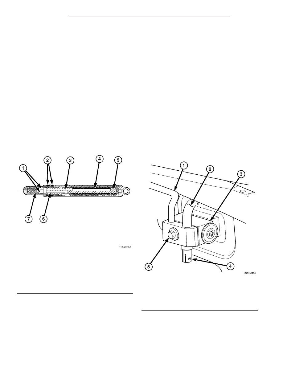
Fig. 11 Variable Orifice Valve

1 - FIXED AND VARIABLE ORIFICES
2 - O-RINGS
3 - FIXED PORT
4 - BIMETAL COIL
5 - INLET FILTER SCREEN
6 - VARIABLE PORT
7 - DIFFUSER SCREEN

Fig. 12 Expansion Valve - 2.4L & RHD Models

1 - LIQUID LINE
2 - SUCTION LINE
3 - A/C EXPANSION VALVE
4 - A/C LOW PRESSURE SWITCH
5 - BOLT

24 - 48

PLUMBING

PL/SRT-4

enters the A/C evaporator. A mechanical sensor in the
A/C expansion valve monitors the temperature and
pressure of the refrigerant leaving the A/C evapora-
tor through the suction line, and adjusts the orifice
size at the liquid line port to let the proper amount
of refrigerant into the A/C evaporator to meet the
vehicle A/C cooling requirements. Controlling the
refrigerant flow through the A/C evaporator ensures
that none of the refrigerant leaving the A/C evapora-
tor is still in a liquid state, which could damage the
A/C compressor.

The A/C expansion valve is factory calibrated and

cannot be adjusted or repaired and, if faulty or dam-
aged, it must be replaced.

DIAGNOSIS AND TESTING

A/C EXPANSION VALVE

WARNING: Refer to the applicable warnings and
cautions for this system before performing the fol-
lowing operation (Refer to 24 - HEATING & AIR
CONDITIONING/PLUMBING - WARNINGS) and (Refer
to 24 - HEATING & AIR CONDITIONING/PLUMBING -
CAUTIONS). Failure to follow the warnings and cau-
tions could result in possible personal injury or
death.

NOTE: The A/C expansion valve should only be
tested following testing of the A/C compressor.

NOTE: Liquid CO

2

is required to test the A/C expan-

sion valve. This material is available from most
welding supply facilities. Liquid CO

2

is also avail-

able from companies which service and sell fire
extinguishers.

When testing the A/C expansion valve, the work

area and the vehicle temperature must be 21° to 27°
C (70° to 85° F). To test the expansion valve:

(1) Connect a charging station or manifold gauge

set to the refrigerant system service ports. Verify the
refrigerant charge level.

(2) Close all doors, windows and vents to the pas-

senger compartment.

(3) Set the A/C-heater controls so that the A/C

compressor is operating, the temperature control is
in the highest temperature position, the mode-air
doors is directing air output to the floor and the
blower motor operating is operating at the highest
speed.

(4) Start the engine and allow it to idle. After the

engine has reached normal operating temperature,
allow the passenger compartment to heat up. This

will create the need for maximum refrigerant flow
into the A/C evaporator.

(5) If the refrigerant charge is sufficient, the dis-

charge (high pressure) gauge should read 827 kPa to
1655 kPa (120 psi to 240 psi). The suction (low pres-
sure) gauge should read 207 kPa to 345 kPa (30 psi
to 50 psi). If OK, go to Step 6. If not OK, replace the
faulty A/C expansion valve.

WARNING:
Protect the skin and eyes from exposure to liquid
CO

2

or personal injury can result.

(6) If the suction (low pressure) gauge reads

within the specified range, freeze the A/C expansion
valve for 30 seconds using liquid CO

2

or another suit-

able super-cold material.Do not spray R-134a or
R-12 refrigerant on the A/C expansion valve for
this test. 
The suction (low pressure) gauge reading
should drop by 69 kPa (10 psi). If OK, go to Step 7 If
not OK, replace the faulty A/C expansion valve.

(7) Allow the expansion valve control head to thaw.

The suction (low pressure) gauge reading should sta-
bilize at 207 kPa to 345 kPa (30 psi to 50 psi). If not
OK, replace the faulty A/C expansion valve.

(8) When expansion valve testing is complete, test

the overall A/C system performance (Refer to 24 -
HEATING & AIR CONDITIONING - DIAGNOSIS
AND TESTING - A/C PERFORMANCE TEST).

REMOVAL

WARNING: Refer to the applicable warnings and
cautions for this system before performing the fol-
lowing operation (Refer to 24 - HEATING & AIR
CONDITIONING/PLUMBING - WARNING - A/C SYS-
TEM) and (Refer to 24 - HEATING & AIR CONDI-
TIONING/PLUMBING - CAUTION - A/C SYSTEM).

(1) Recover the refrigerant from the refrigerant

system (Refer to 24 - HEATING & AIR CONDITION-
ING/PLUMBING

-

STANDARD

PROCEDURE

-

REFRIGERANT SYSTEM RECOVERY).

(2) Disconnect and isolate the negative battery

cable.

(3) Disconnect the wire harness connector from the

A/C low pressure switch (Fig. 13).

(4) Remove the bolt that secures the suction and

liquid line fitting to the A/C expansion valve.

(5) Disconnect the suction line and liquid line fit-

tings from the A/C expansion valve and position the
refrigerant lines out of the way.

(6) Remove the gasket from the A/C expansion

valve and discard.

(7) Install plugs in, or tape over the opened suc-

tion line and liquid line fittings and both expansion
valve ports.

PL/SRT-4

PLUMBING

24 - 49

A/C EXPANSION VALVE - 2.4L AND RHD MODELS (Continued)

(8) Remove the two bolts that secure the A/C

expansion valve to the evaporator tube tapping plate.

(9) Remove the A/C expansion valve from the evap-

orator tube tapping plate.

(10) Remove the gasket from the evaporator tube

tapping plate and discard.

(11) Install plugs in, or tape over the opened evap-

orator inlet and outlet tube fittings and both expan-
sion valve ports.

(12) If required, remove the A/C low pressure

switch from the A/C expansion valve.

INSTALLATION

(1) If removed, install the A/C low pressure switch

onto the A/C expansion valve. Tighten the switch
securely.

(2) Remove the tape or plugs from the evaporator

inlet and outlet tube fittings and both ports on the
back of the A/C expansion valve.

(3) Install a new gasket onto the evaporator tube

tapping plate

(4) Position the A/C expansion valve onto the evap-

orator tube tapping plate.

(5) Install the two bolts that secure the A/C expan-

sion valve to the evaporator tube tapping plate plate.
Tighten the bolts to 10 N·m (88 in. lbs.).

(6) Remove the tape or plugs from the liquid and

suction line fittings and both ports on the front of the
A/C expansion valve.

(7) Install a new gasket onto the A/C expansion

valve.

(8) Connect the liquid and suction line fitting to

the A/C expansion valve.

(9) Install the bolt that secures the suction and

liquid line fitting to the A/C expansion valve. Tighten
the bolt to 20 N·m (15 ft. lbs.).

(10) Connect the wire harness connector to the A/C

low pressure switch.

(11) Reconnect the negative battery cable.
(12) Evacuate the refrigerant system (Refer to 24 -

HEATING & AIR CONDITIONING - STANDARD
PROCEDURE - REFRIGERANT SYSTEM EVACU-
ATE).

(13) Recharge the refrigerant system (Refer to 24 -

HEATING & AIR CONDITIONING - STANDARD
PROCEDURE

-

REFRIGERANT

SYSTEM

CHARGE).

ACCUMULATOR - 2.0L LHD
MODELS

DESCRIPTION

An accumulator (Fig. 14) is used on 2.0L LHD

models. The accumulator is mounted in the engine
compartment between the evaporator outlet and the
compressor

suction

port.

An

integral

mounting

bracket is used to secure the accumulator to the right
side rail with a bolt. A threaded fitting on the top of
the accumulator canister provides the port through
which the A/C low pressure switch monitors the
refrigerant system pressures.

The accumulator cannot be repaired and, if faulty

or damaged, it must be replaced. The suction and liq-
uid lines, the rubber O-rings and the A/C low pres-
sure switch are available for service replacement.

OPERATION

Refrigerant enters the accumulator through the

inlet tube as a low pressure vapor. Any liquid, oil-
laden refrigerant falls to the bottom of the accumu-
lator, which acts as a separator. A desiccant bag
located inside the accumulator absorbs any moisture
which may have entered and become trapped within
the refrigerant system.

Fig. 13 A/C Expansion Valve - 2.4L Shown, RHD

Typical

1 - RECIEVER/DRIER
2 - SERVICE PORTS
3 - RECIEVER/DRIER MOUNTING GROMMET
4 - EVAPORATOR TAPPING BLOCK
5 - A/C EXPANSION VALVE
6 - A/C LOW PRESSURE SWITCH CONNECTOR
7 - HVAC HOUSING DRAIN OUTLET
8 - CONDENSATE DRAIN TUBE
9 - SCREW (2)
10 - LIQUID LINE
11 - SUCTION LINE

24 - 50

PLUMBING

PL/SRT-4

A/C EXPANSION VALVE - 2.4L AND RHD MODELS (Continued)

REMOVAL

WARNING: Review the warnings and cautions in the
front of this section before performing the following
operation (Refer to 24 - HEATING & AIR CONDI-
TIONING/PLUMBING - WARNING - A/C SYSTEM) and
(Refer to 24 - HEATING & AIR CONDITIONING/
PLUMBING - CAUTION - A/C SYSTEM).

(1) Recover the refrigerant from the refrigerant

system (Refer to 24 - HEATING & AIR CONDITION-
ING/PLUMBING

-

STANDARD

PROCEDURE

-

REFRIGEANT SYSTEM RECOVERY).

(2) Disconnect and isolate the negative battery

cable.

(3) If equipped, relocate the vehicle speed control

servo as necessary to access the accumulator (Refer
to 8 - ELECTRICAL/SPEED CONTROL/SERVO -
REMOVAL).

(4) Disconnect the wire harness connector from the

A/C low pressure switch (Fig. 15).

(5) Remove the two nuts that secure the suction

line fittings to the accumulator.

(6) Remove the O-ring seals from the opened suc-

tion line fittings and discard.

(7) Install plugs in, or tape over the opened suc-

tion line fittings and accumulator ports.

(8) Remove the bolt that secures the accumulator

mounting bracket to the body.

(9) Remove the accumulator from the engine com-

partment.

(10) If necessary, remove the A/C low pressure

switch from the accumulator (Refer to 24 - HEATING
&

AIR

CONDITIONING/CONTROLS/A/C

LOW

PRESSURE SWITCH - REMOVAL).

INSTALLATION

NOTE: If the accumulator is replaced, add 30 milli-
liters (1 fluid ounce) of refrigerant oil to the refrig-
erant system. Use only refrigerant oil of the type
recommended for the A/C compressor in the vehi-
cle.

(1) If removed, install the A/C low pressure switch

onto the accumulator using a new O-ring seal.
Tighten the switch securely.

Fig. 14 Accumulator - Typical

1 - A/C LOW PRESSURE SWITCH
2 - PRESSURE SWITCH FITTING
3 - OUTLET TO COMPRESSOR
4 - ANTI-SIPHON HOLE
5 - DESICCANT BAG
6 - OIL RETURN ORIFICE FILTER
7 - VAPOR RETURN TUBE
8 - ACCUMULATOR DOME
9 - O-RING SEAL
10 - INLET FROM EVAPORATOR

Fig. 15 Accumulator - LHD Models Only

1 - LIQUID LINE MOUNTING CLIP
2 - A/C CHARGE PORT
3 - A/C LOW PRESSURE SWITCH
4 - A/C LOW PRESSURE SWITCH CONNECTOR
5 - ACCUMULATOR

PL/SRT-4

PLUMBING

24 - 51

ACCUMULATOR - 2.0L LHD MODELS (Continued)


Content   ..  433  434  435  436   ..