Dodge Neon / Neon SRT-4. Manual - part 434


  Index      Dodge     Dodge Neon / Neon SRT-4 - service repair manual 2005 year


Search            


Content   ..  432  433  434  435   ..


Dodge Neon / Neon SRT-4. Manual - part 434


(3) Remove the accessory drive belt (Refer to 7 -

COOLING/ACCESSORY

DRIVE/DRIVE

BELTS

-

REMOVAL).

(4) Raise and support the vehicle.
(5) Disconnect the engine wire harness connectors

from the compressor clutch coil and the A/C high
pressure switch.

(6) Remove the bolts that secures the suction line

and discharge line to the A/C compressor (Fig. 5).

(7) Disconnect the suction line and discharge line

from the A/C compressor and remove and discard the
O-ring seals.

(8) Install plugs in, or tape over the opened A/C

compressor ports and the refrigerant line fittings.

(9) Support the A/C compressor and remove the

A/C compressor mounting bolts (Fig. 6).

(10) Remove the A/C compressor from the engine

compartment.

INSTALLATION

NOTE: If a replacement A/C compressor is being
installed, be certain to check the refrigerant oil level
(refer to Refrigerant Oil Level in this group). Use
only refrigerant oil of the type recommended for the
A/C compressor in the vehicle.

(1) Position the A/C compressor into the engine

compartment.

(2) Install the four bolts that secure the A/C com-

pressor to the mounting bracket. Tighten the bolts to
28 N·m (21 ft. lbs.).

(3) Remove the tape or plugs from the A/C com-

pressor ports and the refrigerant line fittings.

(4) Lubricate new rubber O-ring seals with clean

refrigerant oil and install them on the refrigerant
line fittings. Use only the specified O-ring seals as
they are made of a special material for the R-134a
system. Use only refrigerant oil of the type recom-
mended for the A/C compressor in the vehicle.

(5) Install the suction line and the discharge line

to the A/C compressor.

(6) Install the bolts that secure the suction line

and the discharge line to the A/C compressor. Tighten
the bolts to 12 N·m (108 in. lbs.).

(7) Connect the engine wire harness connectors to

the compressor clutch coil connector and the A/C high
pressure switch.

(8) Lower the vehicle.
(9) Install the accessory drive belt (Refer to 7 -

COOLING/ACCESSORY

DRIVE/DRIVE

BELTS

-

INSTALLATION).

(10) Reconnect the negative battery cable.
(11) Evacuate the refrigerant system (Refer to 24 -

HEATING & AIR CONDITIONING - STANDARD
PROCEDURE - REFRIGERANT SYSTEM EVACU-
ATE).

(12) Charge the refrigerant system (Refer to 24 -

HEATING & AIR CONDITIONING - STANDARD
PROCEDURE

-

REFRIGERANT

SYSTEM

CHARGE).

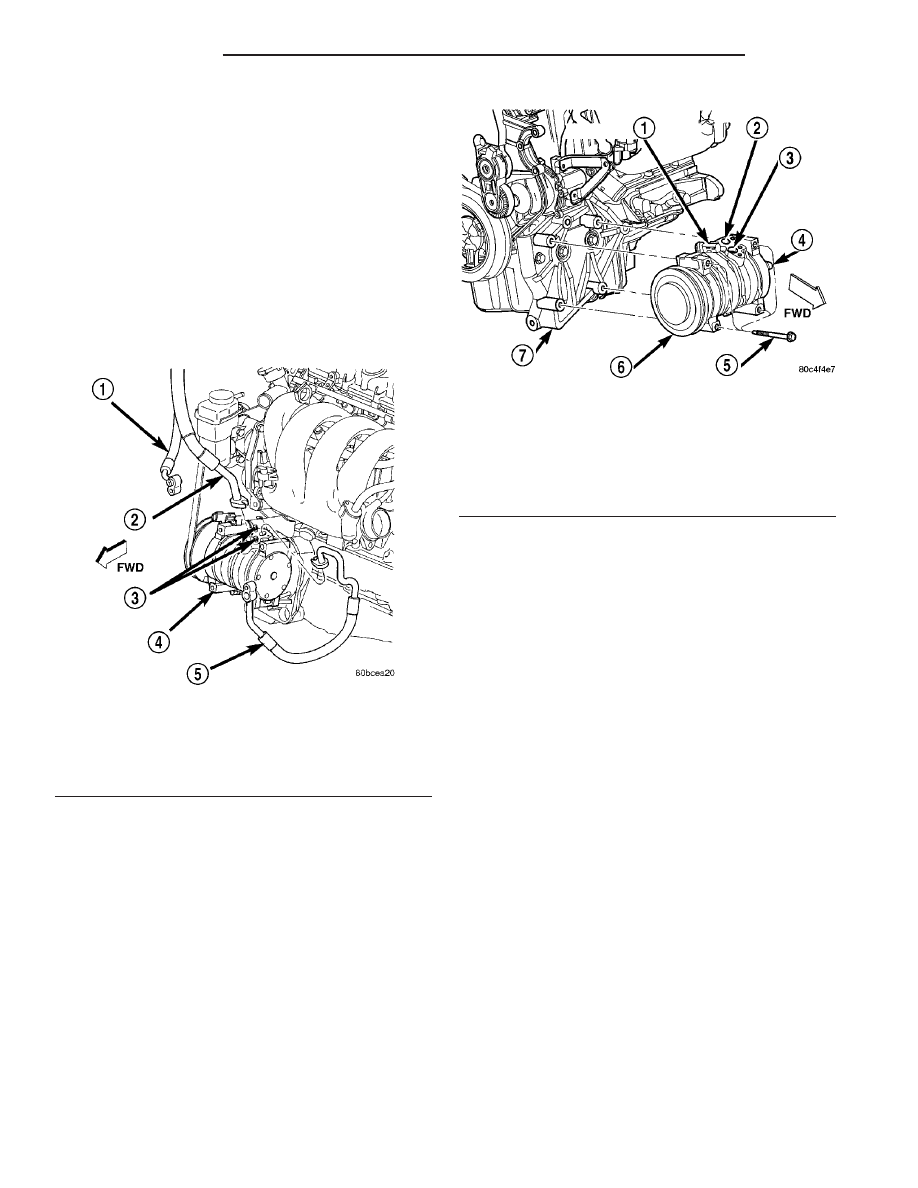
Fig. 5 A/C Compressor Lines

1 - LIQUID LINE
2 - SUCTION LINE
3 - BOLTS (2)
4 - A/C COMPRESSOR
5 - DISCHARGE LINE

Fig. 6 A/C Compressor - Typical

1 - CLUTCH COIL WIRE CONNECTOR
2 - DISCHARGE PORT
3 - SUCTION PORT
4 - HIGH PRESSURE CUT-OUT SWITCH
5 - BOLT (4)
6 - A/C COMPRESSOR
7 - BRACKET

24 - 44

PLUMBING

PL/SRT-4

A/C COMPRESSOR (Continued)

A/C CONDENSER

DESCRIPTION

The A/C condenser is located in the front of the

engine cooling radiator. The A/C condenser is a heat
exchanger that allows the high-pressure refrigerant
gas being discharged by the A/C compressor to give
up its heat to the air passing over the condenser fins.

The A/C condenser is integral to the cooling module

which includes the radiator, electric cooling fan, fan
shroud, air seals and an automatic transmission oil
cooler on models so equipped.

OPERATION

When air passes through the condenser fins, the

high-pressure refrigerant gas within the A/C con-
denser gives up its heat. The refrigerant then con-
denses as it leaves the A/C condenser and becomes a
high-pressure liquid. The volume of air flowing over
the condenser fins is critical to the proper cooling
performance of the air conditioning system. There-
fore, it is important that there are no objects placed
in front of the radiator grille openings at the front of
the vehicle or foreign material on the condenser fins
that might obstruct proper air flow. Also, any factory-
installed air seals or shrouds must be properly rein-
stalled following radiator or A/C condenser service.

The A/C condenser cannot be repaired and, if

faulty or damaged, it must be replaced.

REMOVAL

WARNING: Review the warnings and cautions in the
front of this section before performing the following
operation (Refer to 24 - HEATING & AIR CONDI-
TIONING/PLUMBING - WARNING - A/C SYSTEM) and
(Refer to 24 - HEATING & AIR CONDITIONING/
PLUMBING - CAUTION - A/C SYSTEM).

(1) Disconnect and isolate the negative battery

cable.

(2) Recover the refrigerant from the refrigerant

system (Refer to 24 - HEATING & AIR CONDITION-
ING/PLUMBING

-

STANDARD

PROCEDURE

-

REFRIGERANT SYSTEM RECOVERY).

(3) Remove the battery support strut.
(4) Remove the bolts that secures the discharge

line and the liquid line to the A/C condenser (Fig. 7).

(5) Disconnect the discharge line and the liquid

line from the A/C condenser and remove and discard
the O-ring seals.

(6) Install plug in, or tape over the opened refrig-

erant line fittings and the condenser ports.

(7) Remove upper radiator mounts.
(8) Remove the screws that secure the A/C con-

denser to the radiator.

(9) Carefully tilt the radiator rearward and remove

the A/C condenser from the engine compartment.

INSTALLATION

NOTE: If the A/C condenser is being replaced, add
30 milliliters (1 fluid ounce) of refrigerant oil to the
refrigerant system. Use only refrigerant oil of the
type recommended for the A/C compressor in the
vehicle.

(1) Tilt the radiator back and position the A/C con-

denser into the engine compartment.

(2) Install the screws that secure the A/C con-

denser to the radiator. Tighten the screws to 2 N·m
(17 in. lbs.).

(3) Install the upper radiator mounts.
(4) Remove the tape or plug from the condenser

ports and the refrigerant line fittings.

(5) Lubricate new rubber O-ring seals with clean

refrigerant oil and install them on the refrigerant
line fittings.

(6) Connect the discharge line and the liquid line

to the A/C condenser.

(7) Install the bolts that secures the discharge line

and the liquid line to the A/C condenser. Tighten the
bolts to 12 N·m (108 in. lbs.).

(8) Install the battery support strut.
(9) Evacuate the refrigerant system (Refer to 24 -

HEATING & AIR CONDITIONING/PLUMBING -
STANDARD PROCEDURE - REFRIGERANT SYS-
TEM EVACUATE)

Fig. 7 A/C Condenser Refrigerant Lines

1 - LIQUID LINE
2 - BOLT (2)
3 - DISCHARGE LINE
4 - A/C CONDENSER

PL/SRT-4

PLUMBING

24 - 45

(10) Recharge the A/C system (Refer to 24 - HEAT-

ING & AIR CONDITIONING - STANDARD PROCE-
DURE - REFRIGERANT SYSTEM CHARGE).

(11) Reconnect the negative battery cable.

A/C DISCHARGE LINE

DESCRIPTION

The A/C discharge line is the refrigerant line that

goes from the A/C compressor to the A/C condenser.
The A/C discharge line has no serviceable parts
except for the rubber O-rings.

The A/C discharge line cannot be repaired and, if

found to be leaking or damaged, it must be replaced.

REMOVAL

WARNING: Review the warnings and cautions in the
front of this section before performing the following
operation (Refer to 24 - HEATING & AIR CONDI-
TIONING/PLUMBING - WARNING - A/C SYSTEM) and
(Refer to 24 - HEATING & AIR CONDITIONING/
PLUMBING - CAUTION - A/C SYSTEM).

(1) Disconnect and isolate the negative battery

cable.

(2) Recover the refrigerant from the refrigerant

system (Refer to 24 - HEATING & AIR CONDITION-
ING/PLUMBING

-

STANDARD

PROCEDURE

-

REFRIGERANT SYSTEM RECOVERY).

(3) Remove the bolt that secures the A/C discharge

line to the A/C compressor (Fig. 8).

(4) Disconnect the A/C discharge line from the A/C

compressor and remove and discard the O-ring seal.

(5) Install plug in, or tape over the opened dis-

charge line fitting and the compressor discharge port.

(6) Raise the vehicle on a hoist.
(7) Remove the bolt that secures the A/C discharge

line to the A/C condenser.

(8) Disconnect the A/C discharge line from the A/C

condenser and remove and discard the O-ring seal.

(9) Install plug in, or tape over the opened dis-

charge line fitting and the condenser inlet port.

INSTALLATION

NOTE: Replacement of the refrigerant line O-ring
seals is required anytime a refrigerant line is
opened. Failure to replace the rubber O-ring seals
could result in a refrigerant system leak.

(1) Position the A/C discharge line into the engine

compartment.

(2) Remove the tape or plugs from the condenser

inlet port and the discharge line fitting.

(3) Lubricate a new rubber O-ring seal with clean

refrigerant oil and install it on the discharge line fit-
ting.

(4) Connect the A/C discharge line to the A/C con-

denser.

(5) Install the bolt that secures the A/C discharge

line to the A/C condenser. Tighten the bolt to 12 N·m
(108 in. lbs.).

(6) Lower the vehicle.
(7) Remove the tape or plugs from the compressor

discharge port and the discharge line fitting.

(8) Lubricate a new rubber O-ring seal with clean

refrigerant oil and install it on the discharge line fit-
ting.

(9) Connect the discharge line fitting to the com-

pressor discharge port on the top of the compressor.

(10) Install the bolt that secures the discharge line

fitting to the compressor. Tighten the bolt to 12 N·m
(108 in. lbs.).

(11) Evacuate the refrigerant system (Refer to 24 -

HEATING & AIR CONDITIONING - STANDARD
PROCEDURE - REFRIGERANT SYSTEM EVACU-
ATE).

(12) Recharge the refrigerant system (Refer to 24 -

HEATING & AIR CONDITIONING - STANDARD
PROCEDURE

-

REFRIGERANT

SYSTEM

CHARGE).

(13) Reconnect the negative battery cable.

Fig. 8 A/C Compressor Lines - Typical

1 - LIQUID LINE
2 - SUCTION LINE
3 - BOLTS (2)
4 - A/C COMPRESSOR
5 - DISCHARGE LINE

24 - 46

PLUMBING

PL/SRT-4

A/C CONDENSER (Continued)

A/C EVAPORATOR

DESCRIPTION

The evaporator (Fig. 9) is located in the HVAC

housing, behind the instrument panel. The evapora-
tor is positioned in the housing so that all air that
enters the housing must pass over the fins of the
evaporator coils before it is distributed through the
system ducts and outlets. However, air passing over
the evaporator fins will only be conditioned when the
compressor is engaged and circulating refrigerant
through the evaporator tubes.

OPERATION

Refrigerant enters the evaporator from the variable

orifice valve as a low-temperature, low-pressure liq-
uid. As air flows over the fins of the evaporator, the
humidity in the air condenses on the fins, and the
heat from the air is absorbed by the refrigerant. Heat
absorption causes the refrigerant to boil and vapor-
ize. The refrigerant becomes a low-pressure gas when
it leaves the evaporator.

The evaporator cannot be repaired and, if faulty or

damaged, it must be replaced.

REMOVAL

WARNING: On vehicles equipped with airbags, dis-
able the airbag system before attempting any steer-
ing wheel, steering column, or instrument panel
component diagnosis or service. Disconnect and
isolate the battery negative (ground) cable, then
wait two minutes for the airbag system capacitor to
discharge before performing further diagnosis or
service. This is the only sure way to disable the air-

bag system. Failure to take the proper precautions
could result in an accidental airbag deployment and
possible personal injury or death.

WARNING: Review safety precautions and warnings
in this group before performing this procedure
(Refer to 24 - HEATING & AIR CONDITIONING/
PLUMBING - WARNINGS) and (Refer to 24 - HEAT-
ING & AIR CONDITIONING/PLUMBING - CAUTIONS).
Failure to follow the warnings and cautions could
result in possible personal injury or death.

(1) Remove the HVAC housing (Refer to 24 -

HEATING & AIR CONDITIONING/DISTRIBUTION/
HVAC HOUSING - REMOVAL).

(2) Disassemble the HVAC housing to access the

A/C evaporator (Refer to 24 - HEATING & AIR CON-
DITIONING/DISTRIBUTION/HVAC

HOUSING

-

DISASSEMBLY).

(3) Lift the A/C evaporator out of the lower half of

the HVAC housing (Fig. 10).

INSTALLATION

NOTE: If the evaporator is being replaced, add 60
milliliters (2 fluid ounces) of refrigerant oil to the
refrigerant system.

(1) Install the evaporator coil into the bottom half

of the HVAC housing.

(2) Assemble the HVAC housing (Refer to 24 -

HEATING & AIR CONDITIONING/DISTRIBUTION/
HVAC HOUSING - ASSEMBLY).

(3) Install the HVAC housing (Refer to 24 - HEAT-

ING & AIR CONDITIONING/DISTRIBUTION/HVAC
HOUSING - INSTALLATION).

Fig. 9 Evaporator - LHD Shown, RHD Typical

1 - FOAM WRAP
2 - EVAPORATOR
3 - LOWER HVAC HOUSING
4 - BLOWER MOTOR AND WHEEL

Fig. 10 A/C Evaporator - Typical

1 - A/C EVAPORATOR
2 - LOWER HVAC HOUSING

PL/SRT-4

PLUMBING

24 - 47


Content   ..  432  433  434  435   ..