Dodge Neon / Neon SRT-4. Manual - part 427
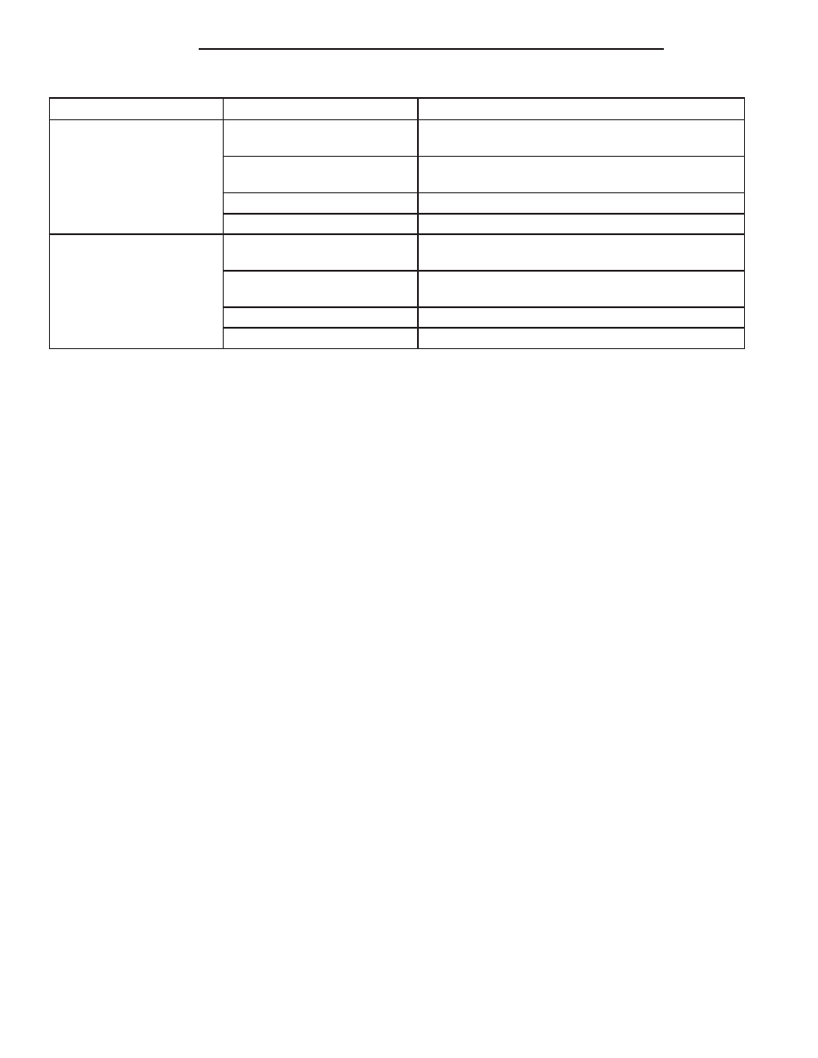
Condition
Possible Causes
Correction
No Forced Air in Panel
Position
1. Vacuum line pinched or
leaking.
1. Locate and repair vacuum leak or pinched line.
2. Faulty mode door.
2. Test actuator and door operation. Repair as
necessary.
3. Faulty selector switch.
3. Test selector switch and replace if necessary.
4. Vacuum check valve.
4. Test check valve and replace if necessary.
No Forced Air in Defrost
Position
1. Vacuum line pinched or
leaking.
1. Locate and repair vacuum leak or pinched line.
2. Faulty heat , defroster, or
mode door.
2. Test actuators and door operation. Repair as
necessary.
3. Faulty selector switch.
3. Test selector switch and replace if necessary.
4. Vacuum check valve.
4. Test check valve and replace if necessary.
ONE-WAY CHECK VALVE
(1) Disconnect the heating-A/C system vacuum
supply (black) line in the engine compartment. This
line passes through an opening in the dash panel.
(2) Remove the one-way vacuum check valve. The
valve is located on the vacuum supply (black) line at
the power brake booster.
(3) Connect the Vacuum Test Probe from the Vac-
uum Test Set to the heater side of the one-way vac-
uum check valve. When connected to this side of the
check valve, no vacuum should pass and the Vacuum
Test Gauge should return to the 27 kPa (8 in. Hg.)
setting. If OK, go to step Step 4. If not OK, replace
the faulty one-way vacuum check valve.
(4) Connect the Vacuum Test Probe from the Vac-
uum Test Set to the engine side of the one-way vac-
uum check valve. When connected to this side of the
check valve, vacuum should flow through the valve
without restriction. If not OK, replace the faulty one-
way vacuum check valve.
A/C-HEATER CONTROLS
NOTE: The operation of the recirculation-air door
can be viewed by removing the blower motor and
looking up into the HVAC housing (Refer to 24 -
HEATING
&
AIR
CONDITIONING/DISTRIBUTION/
BLOWER MOTOR - REMOVAL).
(1) Connect the Vacuum Test Probe to the vehicle
vacuum supply (black) line. Position the Vacuum Test
Gauge so it can be viewed from the passenger com-
partment.
(2) Start with the mode control in the Panel posi-
tion and the recirculation control in the Outside-air
position.
(3) Move the recirculation control to the Recircula-
tion position (the recirculation-air door should move
to the Recirculation position). After a short pause
move the mode control to the Defrost position (the
recirculation-air door should move to the Outside-air
position). The Vacuum Test Gauge should return to
the calibrated setting of 27 kPa (8 in. Hg.) after each
selection is made. If the Vacuum Test Gauge cannot
achieve the calibrated setting, the vacuum circuit or
a component has a vacuum leak.
(4) If the Vacuum Test Gauge achieves the cali-
brated setting but the recirculation-air door does not
move, there is either a pinched vacuum line or a
failed recirculation door actuator.
LOCATING VACUUM LEAKS
(1) Connect the Vacuum Test Probe to the vehicle
vacuum supply (black) line. Position the Vacuum Test
Gauge so it can be viewed from the passenger com-
partment.
(2) Place the mode control in the Panel position
and the recirculation control in the Recirculation
position.
(3) Remove the center instrument panel bezel.
(4) Remove the center vent duct.
(5) Remove and block the vehicle vacuum supply
(black) line at the A/C-heater control. The Vacuum
Test Gauge should return to the calibrated setting of
27 kPa (8 in. Hg). If not, there is a leak in the vac-
uum supply line.
(6) If there is no leak in the vacuum supply (black)
line, reconnect it to the A/C-heater control and
remove the actuator vacuum feed (red) line from the
A/C-heater control. Block the vacuum connection on
the A/C-heater control from where the line was
removed. The Vacuum Test Gauge should return to
the calibrated setting of 27 kPa (8 in. Hg.). If not,
there is a leak in the A/C-heater control.
NOTE: The vacuum port for the recirculation door
actuator is accessible from behind the glove box.
24 - 16
CONTROLS
PL/SRT-4
A/C HEATER CONTROL (Continued)