Dodge Neon / Neon SRT-4. Manual - part 425
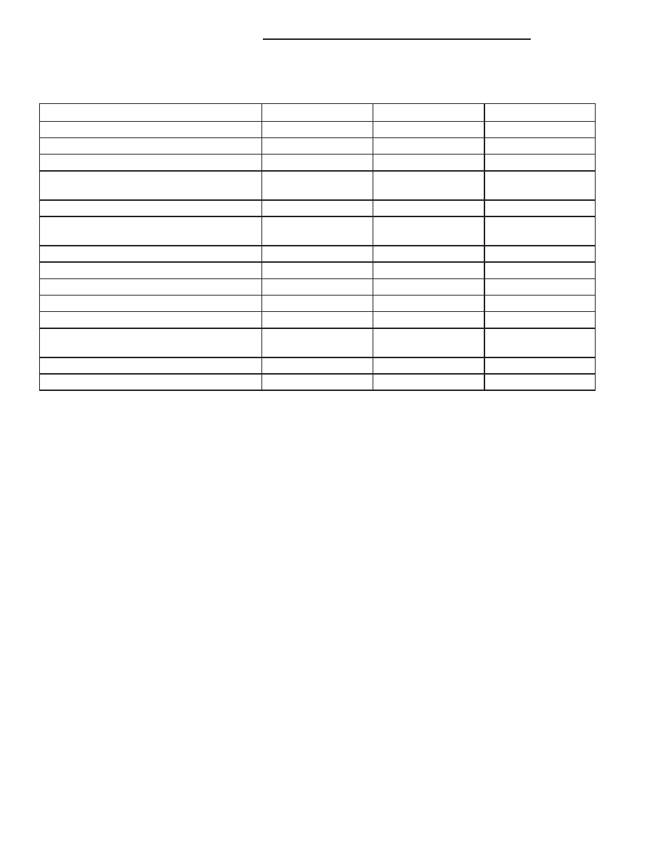
FASTENER TORQUE
Description
N·m
Ft. Lbs.
In. Lbs.
All Screws NOT Listed Below
2
–
17
A/C Compressor Shaft Bolt
17.5
–
155
A/C Compressor Mounting Bolts
28
21
–
A/C Expansion Valve Bolts - 2.4L/RHD
models
10
–
88
Accumulator Mounting Bracket Bolt
11
–
97
Refrigerant Lines/Expansion Valve to
Evaporator Tapping Plate Bolts
10
–
88
Discharge Line to Compressor Bolt
12
–
108
Discharge Line to Condenser Bolt
12
–
108
HVAC Housing Outboard Bolt
4.5
–
40
HVAC Housing Stud Nuts
4.5
–
40
Liquid Line to Condenser Bolt
12
–
108
Refrigerant Lines to Expansion Valve Bolt -
2.4L/RHD models
20
15
–
Suction Line Mid-Line Connector Block Nut
4.5
–
40
Suction Line to Compressor Bolt
12
–
108
24 - 8
HEATING & AIR CONDITIONING
PL/SRT-4
HEATING & AIR CONDITIONING (Continued)