Dodge Neon / Neon SRT-4. Manual - part 331


  Index      Dodge     Dodge Neon / Neon SRT-4 - service repair manual 2005 year


Search            


Content   ..  329  330  331  332   ..


Dodge Neon / Neon SRT-4. Manual - part 331


(5) Remove 5th gear nut with wrench 8478 (Fig.

132). Discard nut and use a new one upon assembly.

(6) Remove 5th gear with arbor press and bearing

splitter.

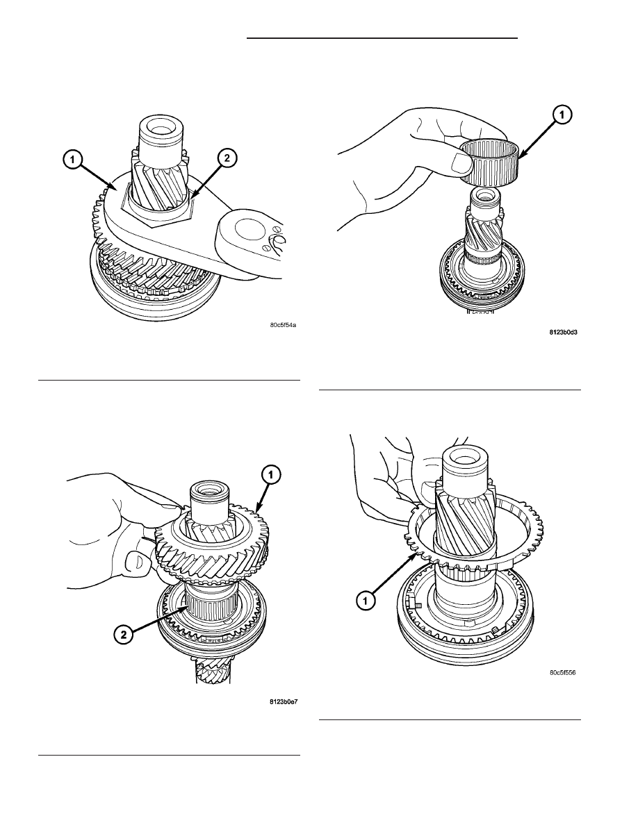
(7) Remove 4th gear and needle bearing (Fig. 133)

(Fig. 134).

(8) Remove 4th gear blocker ring (Fig. 135).

Fig. 132 5th Gear Nut Removal/Installation

1 - WRENCH 8478
2 - 5TH GEAR NUT

Fig. 133 4th Gear Removal/Installation

1 - 4TH GEAR
2 - NEEDLE BEARING

Fig. 134 4th Gear Needle Bearing Removal/

Installation

1 - 4TH GEAR NEEDLE BEARING

Fig. 135 4th Gear Blocker Ring

1 - 4th GEAR BLOCKER RING

21 - 108

T850 MANUAL TRANSAXLE

PL/SRT-4

INPUT SHAFT (Continued)

(9) Remove 3/4 synchronizer snap ring (Fig. 136).

Discard and replace with new snap ring upon assem-
bly.

(10) Remove 3/4 synchronizer (Fig. 137).

(11) Remove 3rd gear blocker ring (Fig. 138).

(12) Remove 3rd gear and needle bearing (Fig.

139) (Fig. 140).

Fig. 136 3/4 Synchro Snap Ring

1 - SNAP RING
2 - 3/4 SYNCHRONIZER

Fig. 137 3/4 Synchro Assembly

1 - 3/4 SYNCHRONIZER

Fig. 138 3rd Gear Blocker Ring

1 - 3RD GEAR BLOCKER RING

Fig. 139 3rd Gear Removal/Installation

1 - 3RD GEAR
2 - NEEDLE BEARING

PL/SRT-4

T850 MANUAL TRANSAXLE

21 - 109

INPUT SHAFT (Continued)

(13) Inspect third gear thrust washer for signs of

excessive wear. To replace, drive off of input shaft
with suitable drift and hammer.

ASSEMBLY

NOTE: When servicing the input shaft assembly, all
snap rings MUST be replaced with new ones upon
assembly. 5th gear nut must also be replaced.

NOTE: When installing 3/4 synchronizer hub to
shaft, make sure to align oil slots on synchronizer
hub face with oil hole in the shaft splined hub jour-
nal.

NOTE: Refer to (Fig. 141) for input shaft assembly
reference.

(1) Install input shaft into fixture 8487.
(2) Install thrust washer if removed upon disas-

sembly.

Fig. 141 Input Shaft Assembly

1 - INPUT SHAFT

7 - SNAP RING

2 - THRUST WASHER

8 - INPUT BEARING (SEALED)

3 - 3RD GEAR

9 - NEEDLE BEARING

4 - 4TH GEAR

10 - SNAP RING

5 - 5TH GEAR

11 - 3/4 SYNCHRONIZER

6 - 5TH GEAR NUT

12 - NEEDLE BEARING

Fig. 140 3rd Gear Needle Bearing Removal/

Installation

1 - 3RD GEAR NEEDLE BEARING
2 - THRUST WASHER

21 - 110

T850 MANUAL TRANSAXLE

PL/SRT-4

INPUT SHAFT (Continued)

(3) Install 3rd gear and needle bearing (Fig. 142)

(Fig. 143).

(4) Install 3rd gear blocker ring (Fig. 144).

(5) Install 3/4 synchronizer (Fig. 145). When

installing 3/4 synchronizer hub to shaft, make
sure to align oil slots on synchronizer hub face
with oil hole in the shaft splined hub journal.

(6) Install NEW 3/4 synchronizer snap ring (Fig.

146).

Fig. 142 3rd Gear Needle Bearing Removal/

Installation

1 - 3RD GEAR NEEDLE BEARING
2 - THRUST WASHER

Fig. 143 3rd Gear Removal/Installation

1 - 3RD GEAR
2 - NEEDLE BEARING

Fig. 144 3rd Gear Blocker Ring

1 - 3RD GEAR BLOCKER RING

Fig. 145 3/4 Synchro Assembly

1 - 3/4 SYNCHRONIZER

PL/SRT-4

T850 MANUAL TRANSAXLE

21 - 111

INPUT SHAFT (Continued)


Content   ..  329  330  331  332   ..