Dodge Neon / Neon SRT-4. Manual - part 316


  Index      Dodge     Dodge Neon / Neon SRT-4 - service repair manual 2005 year


Search            


Content   ..  314  315  316  317   ..


Dodge Neon / Neon SRT-4. Manual - part 316


SHIFT RAIL BUSHINGS

REMOVAL

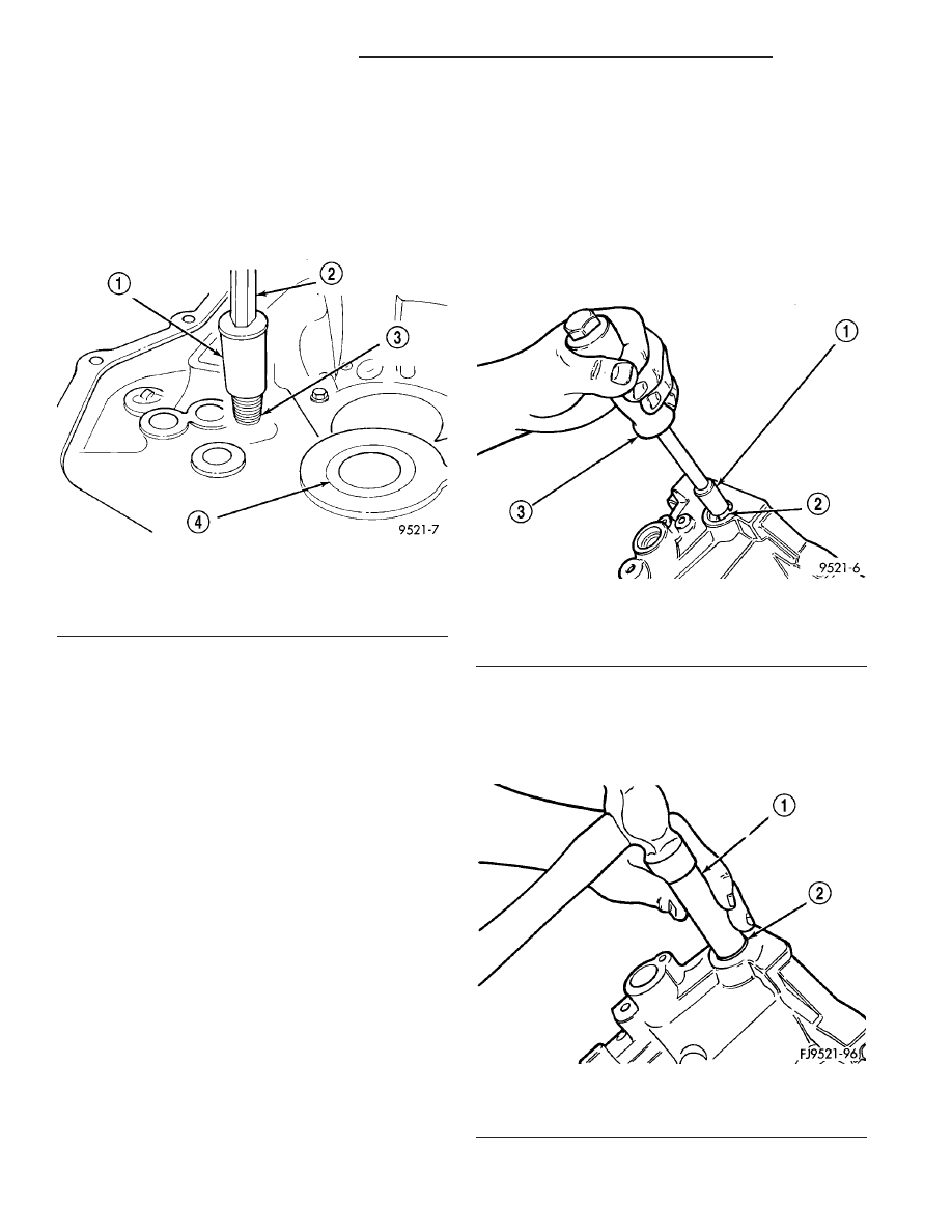
(1) Thread tool #6786 into shift rail bushing.
(2) Install slide hammer #3752 onto tool.
(3) Remove bushing using slide hammer and tool

assembly (Fig. 142).

INSTALLATION

(1) Line up replacement bushing in bore.
(2) Using tool #MD998343, tap bushing into bore

until flush with the chamfer in the case.

SHIFT SELECTOR SHAFT

REMOVAL

(1) Disassemble transaxle.
(2) With the transaxle disassembled, remove the

selector shaft by pushing on the shaft from the out-
side. Pull shaft out from the inside.

INSTALLATION

(1) Pull selector shaft into position from the out-

side.

(2) Assemble transaxle.

SHIFT SELECTOR SHAFT
BUSHING

REMOVAL

(1) Remove selector shaft using procedure in this

group.

(2) Thread tool #6786 into bushing.
(3) Install slide hammer #3752 onto tool and

remove bushing using slide hammer (Fig. 143).

INSTALLATION

(1) Position replacement bushing over selector

shaft bore.

(2) Using an appropriate size deep–well socket,

install bushing in selector shaft bore (Fig. 144).

Fig. 142 Shift Rail Bushing Removal

1 - SPECIAL TOOL 6786
2 - SLIDE HAMMER C-3752
3 - SHIFTER RAIL BUSHING
4 - INPUT BEARING

Fig. 143 Selector Shaft Bushing Removal

1 - SPECIAL TOOL 6786
2 - SHIFT SHAFT BUSHING
3 - SLIDE HAMMER C-3752

Fig. 144 Selector Shaft Bushing Installation

1 - DEEP WELL SOCKET
2 - SHIFTER SHAFT BUSHING

21 - 48

T350 MANUAL TRANSAXLE

PL/SRT-4

SHIFT SHAFT SEALS

REMOVAL

It is not necessary to remove the shift shafts from

the transaxle to service the shift shaft seals.

(1) Using a pick tool, pry up on the shift shaft

seal, and remove seal from bore.

INSTALLATION

(1) Position new shift shaft seal into bore.
(2) Install shift shaft seal into bore using an

appropriate size deep-well socket.

SYNCHRONIZER

DISASSEMBLY

Place synchronizer in a clean shop towel and wrap.

Press on inner hub. Carefully open up shop towel
and remove springs, balls, keys, hub, and sleeve.

CLEANING

CLEAN

Do not attempt to clean the blocking rings in sol-

vent. The friction material will become contaminated.
Place synchronizer components in a suitable holder
and clean with solvent. Air dry.

INSPECTION

INSPECT

Proper inspection of components involve:
• Teeth, for wear, scuffed, nicked, burred, or bro-

ken teeth

• Keys, for wear or distortion

• Balls and springs, for distortion, cracks, or wear
If any of these conditions exist in these compo-

nents, replace as necessary.

ASSEMBLY

(1) Position synchronizer hub onto a suitable hold-

ing fixture (input shaft). The synchronizer hubs are
directional. The hubs must be installed with the U
facing upward.

(2) Install springs into hub slot (Fig. 145).

(3) Insert key into hub and spring.
(4) Apply petroleum jelly to the hole in the key.

Insert balls into each key (Fig. 146).

Fig. 145 Synchronizer Assembly

1 - SLEEVE
2 - BALL
3 - KEY
4 - SPRING
5 - HUB

Fig. 146 Synchronizer Balls

1 - INPUT SHAFT
2 - HUB
3 - KEY
4 - BALL

PL/SRT-4

T350 MANUAL TRANSAXLE

21 - 49

(5) Slide sleeve over the hub and depress balls as

you carefully slip the sleeve into position (Fig. 147).

(6) Line up stop ring tang over the keys in the hub

(Fig. 148). Install stop rings. Center the keys and
balls by pushing on both stop rings.

VEHICLE SPEED SENSOR

DESCRIPTION

VEHICLE SPEED SENSOR

The Vehicle Speed Sensor (VSS) is a pulse genera-

tor mounted to an adapter near the transmission out-
put shaft. The sensor is driven through the adapter
by a speedometer pinion gear. The VSS pulse signal
to the speedometer/odometer is monitored by the
PCM speed control circuitry to determine vehicle
speed and to maintain speed control set speed.

REMOVAL

(1) Raise vehicle on hoist.
(2) Disconnect the speed sensor connector (Fig.

149).

CAUTION: Clean area around speed sensor before
removing to prevent dirt from entering the transaxle
during speed sensor removal.

(3) Remove speed sensor retaining bolt (Fig. 149).

(4) Remove speed sensor from transaxle.

Fig. 147 Synchronizer Sleeve

1 - SLEEVE
2 - INPUT SHAFT
3 - KEY

Fig. 148 Keys in Hub

1 - SNAP RING
2 - CLUTCH
3 - KEY
4 - BALL
5 - SPRING

Fig. 149 Speed Sensor and Pinion—Removal/

Installation

1 - CONNECTOR
2 - SENSOR
3 - O-RING
4 - SPEEDO PINION

21 - 50

T350 MANUAL TRANSAXLE

PL/SRT-4

SYNCHRONIZER (Continued)

CAUTION: Carefully remove vehicle speed sensor
so that sensor drive gear does not fall into trans-
axle. Should sensor drive gear fall into the trans-
axle during sensor removal, drive gear must be
reattached to sensor.

(5) Remove speed sensor drive gear from speed

sensor.

INSTALLATION

(1) Install pinion gear to speed sensor (Fig. 149).
(2) Using a NEW o-ring, install the speed sensor

to the transaxle (Fig. 149).

(3) Install the bolt and torque to 7 N·m (60 in.

lbs.).

(4) Connect speed sensor connector (Fig. 149).
(5) Lower vehicle and road test to verify proper

speedometer operation.

PL/SRT-4

T350 MANUAL TRANSAXLE

21 - 51

VEHICLE SPEED SENSOR (Continued)


Content   ..  314  315  316  317   ..