Dodge Neon / Neon SRT-4. Manual - part 306


  Index      Dodge     Dodge Neon / Neon SRT-4 - service repair manual 2005 year


Search            


Content   ..  304  305  306  307   ..


Dodge Neon / Neon SRT-4. Manual - part 306


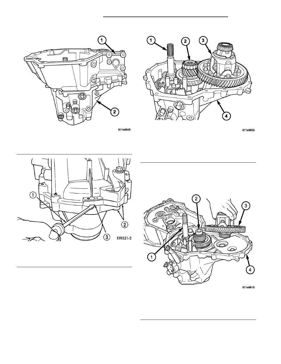
(6) Remove bellhousing half from gear case half

(Fig. 19).

(7) Remove output shaft roller bearing from output

shaft.

(8) Remove differential assembly from housing

(Fig. 20).

(9) Remove reverse idler shaft bolt (Fig. 21).

Fig. 17 Transaxle Case Halves

1 - BELLHOUSING HALF
2 - GEARTRAIN HALF

Fig. 18 Separate Case Halves

1 - PRY TOOL
2 - CASE HALVES
3 - PRY SLOT

Fig. 19 Bellhousing Case Half Removed

1 - INPUT SHAFT
2 - OUTPUT SHAFT
3 - DIFFERENTIAL ASSEMBLY
4 - GEARTRAIN HOUSING

Fig. 20 Differential Removal/Installation

1 - INPUT SHAFT
2 - OUTPUT SHAFT
3 - DIFFERENTIAL ASSEMBLY
4 - GEARTRAIN HOUSING

21 - 8

T350 MANUAL TRANSAXLE

PL/SRT-4

T350 MANUAL TRANSAXLE (Continued)

(10) Remove reverse idler shaft (Fig. 22).
(11) Remove reverse idler gear and spacer (Fig.

23).

(12) Remove two screws retaining reverse fork

bracket (Fig. 24). Remove reverse fork bracket and
reverse cam blockout assembly (Fig. 25).

Fig. 21 Reverse Idler Shaft

1 - CASE
2 - REVERSE IDLER SHAFT
3 - REVERSE IDLER SHAFT BOLT

Fig. 22 Reverse Idler Shaft Removal

1 - REVERSE IDLER SHAFT
2 - SPACER

Fig. 23 Reverse Idler Gear and Spacer

1 - SPACER
2 - REVERSE IDLER GEAR

Fig. 24 Screws Retaining Reverse Fork Bracket

1 - SCREWS (2)
2 - REVERSE FORK BRACKET

PL/SRT-4

T350 MANUAL TRANSAXLE

21 - 9

T350 MANUAL TRANSAXLE (Continued)

(13) Using snap–ring pliers, remove selector shaft

spacer (Fig. 26).

(14) Pull the selector shaft shift pin out of the slot

in the blocker assembly. Turn selector shaft up and
out of the way (Fig. 27).

(15) Remove transaxle end cover (Fig. 28) (Fig.

29).

Fig. 25 Remove Reverse Fork Bracket

1 - REVERSE FORK BRACKET
2 - REVERSE CAM BLOCKOUT
3 - SHIFT BLOCKER ASSEMBLY

Fig. 26 Remove Selector Shaft Spacer

1 - SHIFT BLOCKER ASSEMBLY
2 - SELECTOR SHAFT SPACER (PLASTIC)
3 - SNAP RING PLIERS

Fig. 27 Selector Shaft

1 - SHIFT ASSEMBLY
2 - SELECTOR SHAFT

Fig. 28 Transaxle Cover Removal

1 - TRANSAXLE CASE
2 - END COVER

21 - 10

T350 MANUAL TRANSAXLE

PL/SRT-4

T350 MANUAL TRANSAXLE (Continued)

(16) Remove two snap rings retaining the output

shaft and the input shaft to the bearings (Fig. 30).

(17) Using

bench

fixture

and

shims

provided

(Miller tools # 6785, 6785-1, and 6785-2), turn trans-
axle over. Install transaxle onto bench fixture (Fig.
31). Verify shim spacers are in position on bench fix-
ture. Install transaxle into shop press.

(18) Install bearing fixture Miller tool #6768 onto

transaxle end bearings (Fig. 32). Verify tool is prop-
erly aligned to input and output shafts.

CAUTION: The oil dams in the input and output
shafts can be damaged while pressing on the
shafts if the bearing fixture is not used properly.

(19) Install transaxle gear case into shop press.

Press output and input shaft assemblies out of case
(Fig. 33).

Fig. 29 End Cover

1 - END COVER
2 - CASE

Fig. 30 Snap Rings Retaining Bearings

1 - SNAP RING PLIERS
2 - SNAP RINGS

Fig. 31 Bench Fixture

1 - SHIMS
2 - TRANSAXLE
3 - 6785 BENCH FIXTURE

Fig. 32 Bearing Fixture

1 - BEARING FIXTURE
2 - TRANSAXLE CASE

PL/SRT-4

T350 MANUAL TRANSAXLE

21 - 11

T350 MANUAL TRANSAXLE (Continued)


Content   ..  304  305  306  307   ..