Dodge Neon / Neon SRT-4. Manual - part 287


  Index      Dodge     Dodge Neon / Neon SRT-4 - service repair manual 2005 year


Search            


Content   ..  285  286  287  288   ..


Dodge Neon / Neon SRT-4. Manual - part 287


REMOVAL

REMOVAL - 1.6L

(1) Disconnect the negative battery cable
(2) Raise vehicle and support.
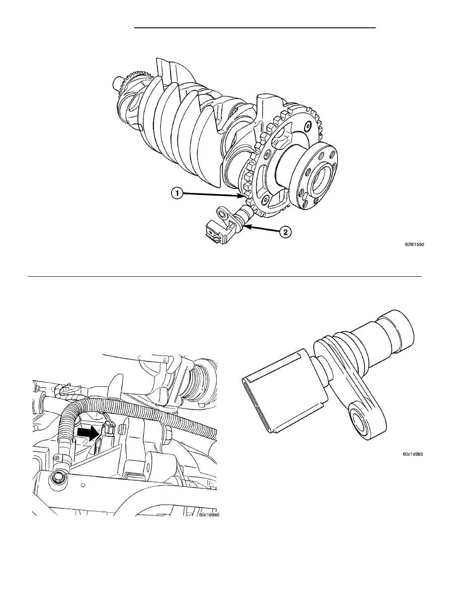
(3) Disconnect the electrical connector (Fig. 15).

(4) Remove bolt from Crankshaft sensor.
(5) Remove sensor (Fig. 16).

REMOVAL - 2.0, 2.4, 2.4L TURBO

The Crankshaft Position Sensor is in the front of

the engine block just under the starter motor (Fig.
17).

(1) Disconnect the negative battery cable.
(2) Raise vehicle and support.
(3) On 2.4L SRT-4 remove the lower inner cooler

hose from the metal tube.

Fig. 14 TIMING REFERENCE NOTCHES (NGC)

1 - Crankshaft

2 - Crankshaft Position Sensor

Fig. 15 CRANKSHAFT SENSOR LOCATION

Fig. 16 CRANKSHAFT POSITION SENSOR

14 - 30

FUEL INJECTION

PL/SRT-4

CRANKSHAFT POSITION SENSOR (Continued)

(4) Remove the Structural Collar (Fig. 18), refer to

the Engine, Structural Collar Removal and Installa-
tion section.

(5) Unlock and disconnect the electrical connector

to the crankshaft position sensor.

(6) Remove the crankshaft position sensor bolt.
(7) Remove the sensor (Fig. 19).

INSTALLATION

INSTALLATION - 1.6L

(1) Install the Crankshaft sensor (Fig. 15).
(2) Install bolt and tighten to 10 N·m (90 in. lbs.).
(3) Connect the electrical connector (Fig. 16).
(4) Lower vehicle.
(5) Connect the negative battery cable.

INSTALLATION - 2.0, 2.4, 2.4L Turbo

(1) Check o-ring for damage and lubricate the

o-ring with engine oil before installing sensor (Fig.
19).

(2) Use a twisting motion when installing the sen-

sor.

(3) Install and tighten the crankshaft position sen-

sor bolt and tighten to 9 N·m (80 ±15 in. lbs.).

(4) Connect and lock the electrical connector to the

crankshaft position sensor.

(5) Install the Structural Collar, refer to the

Engine, Structural Collar Removal and Installation
section (Fig. 18).

(6) On 2.4L SRT-4 install the lower inner cooler

hose to metal tube and tighten clamp.

(7) Lower vehicle.
(8) Connect the negative battery cable.

Fig. 17 CRANKSHAFT POSITION SENSOR

LOCATION

Fig. 18 Structural Collar and Bending Strut—

(Automatic Transaxle Equipped)

1–8 – BOLT TIGHTENING SEQUENCE
9 – TRANSAXLE
10 – COLLAR
11 – OIL PAN
12 – STRUT

Fig. 19 CRANKSHAFT POSITION SENSOR - 2.4 L

TURBO

PL/SRT-4

FUEL INJECTION

14 - 31

CRANKSHAFT POSITION SENSOR (Continued)

FUEL INJECTOR

DESCRIPTION

The injectors are positioned in the intake manifold

with the nozzle ends directly above the intake valve
port (Fig. 20).

OPERATION

The fuel injectors are 12 volt electrical solenoids

(Fig. 21). The injector contains a pintle that closes off
an orifice at the nozzle end. When electric current is
supplied to the injector, the armature and needle
move a short distance against a spring, allowing fuel
to flow out the orifice. Because the fuel is under high
pressure, a fine spray is developed in the shape of a
hollow cone or two streams. The spraying action
atomizes the fuel, adding it to the air entering the
combustion chamber. Fuel injectors are not inter-
changeable between engines.

The PCM provides battery voltage to each injector

through the ASD relay. Injector operation is con-
trolled by a ground path provided for each injector by
the PCM. Injector on-time (pulse-width) is variable,
and is determined by the PCM processing all the
data previously discussed to obtain the optimum
injector pulse width for each operating condition. The
pulse width is controlled by the duration of the
ground path provided.

STANDARD PROCEDURE

REMOVAL - INJECTOR CONNECTOR

(1) Disconnect electrical connectors at the fuel

injectors (Fig. 22). To remove connector refer to (Fig.
23). Pull the red colored slider away from injector (1).
While pulling the slider, depress tab (2) and remove
connector (3) from injector. The factory fuel injection
wiring harness is numerically tagged (INJ 1, INJ 2,
etc.) for injector position identification. If harness is
not tagged, make note of wiring location before
removal.

Fig. 20 Fuel Injector Location—Typical

1 - FUEL RAIL
2 - INTAKE MANIFOLD
3 - FUEL INJECTORS

Fig. 21 FUEL INJECTOR - TYPICAL

1 - FUEL INJECTOR
2 - NOZZLE
3 - TOP (FUEL ENTRY)

Fig. 22 Fuel Injectors

14 - 32

FUEL INJECTION

PL/SRT-4

REMOVAL

(1) Disconnect negative cable from battery.
(2) Release fuel system pressure. Refer to Fuel

System Pressure Release procedure in this section.

(3) Disconnect fuel supply tube from rail. Refer to

Quick-Connect Fittings in the Fuel Delivery section
of this group.

(4) Disconnect electrical connectors from fuel injec-

tors (Fig. 24), refer to the fuel injector connector sec-
tion for electrical connector removal.

(5) Remove fuel rail mounting screws.
(6) Lift rail off of intake manifold. Cover the fuel

injector openings in the intake manifold.

(7) Remove fuel injector retainer (Fig. 25).

(8) Pull injector out of fuel rail. Replace fuel injec-

tor O-rings (Fig. 26).

INSTALLATION

(1) Apply a light coating of clean engine oil to the

upper O-ring.

(2) Install injector in cup on fuel rail.
(3) Install retaining clip.
(4) Apply a light coating of clean engine oil to the

O-ring on the nozzle end of each injector.

Fig. 23 Remove/Install Injector Connector

Fig. 24 Fuel Rail and Injectors

1 - FUEL SUPPLY LINE
2 - FUEL LINE QUICK-CONNECTS
3 - IGNITION COIL
4 - FUEL RAIL
5 - FUEL INJECTOR

Fig. 25 Fuel Injector Retainer

1 - RETAINER
2 - FUEL RAIL
3 - FUEL INJECTOR

Fig. 26 Fuel Injector O-Rings

1 - FUEL INJECTOR
2 - NOZZLE
3 - TOP (FUEL ENTRY)

PL/SRT-4

FUEL INJECTION

14 - 33

FUEL INJECTOR (Continued)


Content   ..  285  286  287  288   ..