Dodge Neon / Neon SRT-4. Manual - part 225


  Index      Dodge     Dodge Neon / Neon SRT-4 - service repair manual 2005 year


Search            


Content   ..  223  224  225  226   ..


Dodge Neon / Neon SRT-4. Manual - part 225


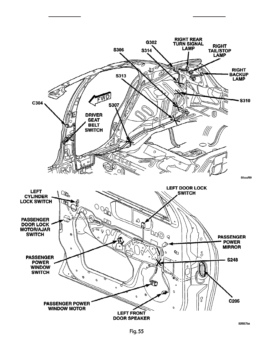
Fig. 54 BODY (RIGHT REAR) - RHD

Fig. 55 DOOR (PASSENGER) - RHD

8W - 91 - 62

8W-91 CONNECTOR/GROUND/SPLICE LOCATION

PL/SRT-4

CONNECTOR/GROUND/SPLICE LOCATION (Continued)

Fig. 56 DOOR (DRIVER) - RHD

Fig. 57 DOOR (REAR) - RHD

PL/SRT-4

8W-91 CONNECTOR/GROUND/SPLICE LOCATION

8W - 91 - 63

CONNECTOR/GROUND/SPLICE LOCATION (Continued)

Fig. 58 DECKLID - RHD

8W - 91 - 64

8W-91 CONNECTOR/GROUND/SPLICE LOCATION

PL/SRT-4

CONNECTOR/GROUND/SPLICE LOCATION (Continued)

8W-97 POWER DISTRIBUTION

TABLE OF CONTENTS

page

page

CIGAR LIGHTER OUTLET

REMOVAL

. . . . . . . . . . . . . . . . . . . . . . . . . . . . . 1

INSTALLATION

. . . . . . . . . . . . . . . . . . . . . . . . . . 1

FUSE BLOCK

DESCRIPTION

. . . . . . . . . . . . . . . . . . . . . . . . . . 1

OPERATION

. . . . . . . . . . . . . . . . . . . . . . . . . . . . 2

REMOVAL

. . . . . . . . . . . . . . . . . . . . . . . . . . . . . 2

INSTALLATION

. . . . . . . . . . . . . . . . . . . . . . . . . . 2

POWER DISTRIBUTION CENTER

DESCRIPTION

. . . . . . . . . . . . . . . . . . . . . . . . . . 2

REMOVAL

. . . . . . . . . . . . . . . . . . . . . . . . . . . . . 2

INSTALLATION

. . . . . . . . . . . . . . . . . . . . . . . . . . 3

CIGAR LIGHTER OUTLET

REMOVAL

(1) Disconnect and isolate the battery negative

cable.

(2) Look inside and note position of the retaining

bosses (Fig. 1).

(3) Using external snap ring pliers with 90 degree

tips. Insert pliers with tips against bosses and
squeeze forcing bosses out of base.

(4) Pull out the base through mounting ring by

gently rocking pliers. A tool can be made to do the
same (Fig. 2).

(5) Disconnect the base wires.
(6) Set base aside and remove base mount ring.

INSTALLATION

(1) Position mount ring to the instrument panel

and feed the wires through ring. Index the cap and
the mount ring with the index tab at 9 o’clock to the
key in the instrument panel. Install the ring.

(2) Connect wires to base. Orient base alignment

rib at 11 o’clock to mate the groove in mount ring at
the same location

(3) Push base into the bezel till it locks.
(4) Install cigar lighter cap and check operation of

element.

(5) Connect the battery negative cable.

FUSE BLOCK

DESCRIPTION

An electrical Fuse Block is located in the left end

of the instrument panel. It serves to simplify and
centralize numerous electrical components, as well as

Fig. 1 CIGAR LIGHTER/POWER OUTLET BASE

REMOVAL

1 - RETAINING BOSSES ENGAGE PLIERS HERE
2 - PARTIALLY REMOVED
3 - EXTERNAL SNAP-RING PLIERS
4 - PULL BASE OUT THROUGH MOUNTING RING

Fig. 2 CIGAR LIGHTER/POWER OUTLET BASE

REMOVAL

1 - 2.5 mm (3/32 inches)
2 - WELD
3 - 100 mm (4 inches)
4 - 22.25 TO 22.45 mm (7/8 TO 57/64 inches)

PL/SRT-4

8W-97 POWER DISTRIBUTION

8W - 97 - 1


Content   ..  223  224  225  226   ..