Dodge Neon / Neon SRT-4. Manual - part 119


  Index      Dodge     Dodge Neon / Neon SRT-4 - service repair manual 2005 year


Search            


Content   ..  117  118  119  120   ..


Dodge Neon / Neon SRT-4. Manual - part 119


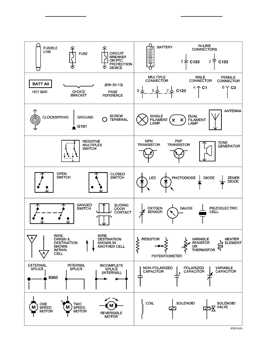
Fig. 3 WIRING DIAGRAM SYMBOLS

8W - 01 - 4

8W-01 WIRING DIAGRAM INFORMATION

PL/SRT-4

WIRING DIAGRAM INFORMATION (Continued)

TERMINOLOGY

This is a list of terms and definitions used in the

wiring diagrams.

LHD . . . . . . . . . . . . . . . . . Left Hand Drive Vehicles
RHD . . . . . . . . . . . . . . . Right Hand Drive Vehicles
ATX . . Automatic Transmissions-Front Wheel Drive
MTX . . . Manual Transmissions-Front Wheel Drive
AT . . . . Automatic Transmissions-Rear Wheel Drive
MT . . . . . Manual Transmissions-Rear Wheel Drive
SOHC . . . . . . . . . . . Single Over Head Cam Engine
DOHC . . . . . . . . . . Double Over Head Cam Engine
Export . . Vehicles Built For Sale In Markets Other

Than North America

Except Export . . . . Vehicles Built For Sale In North

America

DESCRIPTION - CIRCUIT INFORMATION

Each wire shown in the diagrams contains a code

which identifies the main circuit, part of the main
circuit, gage of wire, and color (Fig. 4).

WIRE COLOR CODE CHART

COLOR CODE

COLOR

BL

BLUE

BK

BLACK

BR

BROWN

DB

DARK BLUE

DG

DARK GREEN

GY

GRAY

LB

LIGHT BLUE

LG

LIGHT GREEN

OR

ORANGE

PK

PINK

RD

RED

TN

TAN

VT

VIOLET

WT

WHITE

YL

YELLOW

*

WITH TRACER

Fig. 4 WIRE CODE IDENTIFICATION

1 - COLOR OF WIRE (LIGHT BLUE WITH YELLOW TRACER
2 - GAGE OF WIRE (18 GAGE)
3 - PART OF MAIN CIRCUIT (VARIES DEPENDING ON
EQUIPMENT)
4 - MAIN CIRCUIT IDENTIFICATION

PL/SRT-4

8W-01 WIRING DIAGRAM INFORMATION

8W - 01 - 5

WIRING DIAGRAM INFORMATION (Continued)

DESCRIPTION - CIRCUIT FUNCTIONS

All circuits in the diagrams use an alpha/numeric

code to identify the wire and it’s function. To identify
which circuit code applies to a system, refer to the
Circuit Identification Code Chart. This chart shows
the main circuits only and does not show the second-
ary codes that may apply to some models.

CIRCUIT IDENTIFICATION CODE CHART

CIRCUIT

FUNCTION

A

BATTERY FEED

B

BRAKE CONTROLS

C

CLIMATE CONTROLS

D

DIAGNOSTIC CIRCUITS

E

DIMMING ILLUMINATION
CIRCUITS

F

FUSED CIRCUITS

G

MONITORING CIRCUITS
(GAUGES)

H

MULTIPLE

I

NOT USED

J

OPEN

K

POWERTRAIN CONTROL
MODULE

L

EXTERIOR LIGHTING

M

INTERIOR LIGHTING

N

MULTIPLE

O

NOT USED

P

POWER OPTION (BATTERY
FEED)

Q

POWER OPTIONS (IGNITION
FEED)

R

PASSIVE RESTRAINT

S

SUSPENSION/STEERING

T

TRANSMISSION/TRANSAXLE/
TRANSFER CASE

U

OPEN

V

SPEED CONTROL, WIPER/
WASHER

W

WIPERS

X

AUDIO SYSTEMS

Y

OPEN

Z

GROUNDS

DESCRIPTION - SECTION IDENTIFICATION AND
INFORMATION

The wiring diagrams are grouped into individual

sections. If a component is most likely found in a par-
ticular group, it will be shown complete (all wires,
connectors, and pins) within that group. For exam-
ple, the Auto Shutdown Relay is most likely to be
found in Group 30, so it is shown there complete. It
can, however, be shown partially in another group if
it contains some associated wiring.

Splice diagrams in Section 8W-70 show the entire

splice and provide references to other sections the
splices serves. Section 8W-70 only contains splice dia-
grams that are not shown in their entirety some-
where else in the wiring diagrams.

Section 8W-80 shows each connector and the cir-

cuits involved with that connector. The connectors
are identified using the name/number on the dia-
gram pages.

WIRING SECTION CHART

GROUP

TOPIC

8W-01 thru
8W-09

General information and Diagram
Overview

8W-10 thru
8W-19

Main Sources of Power and
Vehicle Grounding

8W-20 thru
8W-29

Starting and Charging

8W-30 thru
8W-39

Powertrain/Drivetrain Systems

8W-40 thru
8W-49

Body Electrical items and A/C

8W-50 thru
8W-59

Exterior Lighting, Wipers and
Trailer Tow

8W-60 thru
8W-69

Power Accessories

8W-70

Splice Information

8W-80

Connector Pin Outs

8W-91

Connector, Ground and Splice
Locations

8W - 01 - 6

8W-01 WIRING DIAGRAM INFORMATION

PL/SRT-4

WIRING DIAGRAM INFORMATION (Continued)

DESCRIPTION - CONNECTOR, GROUND AND
SPLICE INFORMATION

CAUTION: Not all connectors are serviced. Some
connectors are serviced only with a harness. A typ-
ical example might be the Supplemental Restraint
System connectors. Always check parts availability
before attempting a repair.

IDENTIFICATION

In-line connectors are identified by a number, as

follows:

• In-line connectors located in the engine compart-

ment are C100 series numbers

• In-line connectors located in the Instrument

Panel area are C200 series numbers.

• In-line connectors located in the body are C300

series numbers.

• Jumper harness connectors are C400 series

numbers.

• Grounds and ground connectors are identified

with a “G” and follow the same series numbering as
the in-line connectors.

• Splices are identified with an “S” and follow the

same series numbering as the in-line connectors.

• Component connectors are identified by the com-

ponent name instead of a number. Multiple connec-
tors on a component use a C1, C2, etc. identifier.

LOCATIONS

Section

8W-91

contains

connector/ground/splice

location illustrations. The illustrations contain the
connector name (or number)/ground number/splice
number and component identification. Connector/
ground/splice location charts in section 8W-91 refer-
ence the figure numbers of the illustrations.

The abbreviation T/O is used in the component

location section to indicate a point in which the wir-
ing harness branches out to a component. The abbre-
viation N/S means Not Shown in the illustrations

WARNINGS - GENERAL

WARNINGS provide information to prevent per-

sonal injury and vehicle damage. Below is a list of
general warnings that should be followed any time a
vehicle is being serviced.

WARNING: ALWAYS WEAR SAFETY GLASSES FOR
EYE PROTECTION.

WARNING: USE SAFETY STANDS ANYTIME A PRO-
CEDURE REQUIRES BEING UNDER A VEHICLE.

WARNING: BE SURE THAT THE IGNITION SWITCH
ALWAYS IS IN THE OFF POSITION, UNLESS THE
PROCEDURE REQUIRES IT TO BE ON.

WARNING:

SET

THE

PARKING

BRAKE

WHEN

WORKING

ON

ANY

VEHICLE.

AN

AUTOMATIC

TRANSMISSION SHOULD BE IN PARK. A MANUAL
TRANSMISSION SHOULD BE IN NEUTRAL.

WARNING: OPERATE THE ENGINE ONLY IN A
WELL-VENTILATED AREA.

WARNING: KEEP AWAY FROM MOVING PARTS
WHEN THE ENGINE IS RUNNING, ESPECIALLY THE
FAN AND BELTS.

WARNING: TO PREVENT SERIOUS BURNS, AVOID
CONTACT WITH HOT PARTS SUCH AS THE RADIA-
TOR, EXHAUST MANIFOLD(S), TAIL PIPE, CATA-
LYTIC CONVERTER AND MUFFLER.

WARNING: DO NOT ALLOW FLAME OR SPARKS
NEAR

THE

BATTERY.

GASES

ARE

ALWAYS

PRESENT IN AND AROUND THE BATTERY.

WARNING: ALWAYS REMOVE RINGS, WATCHES,
LOOSE HANGING JEWELRY AND AVOID LOOSE
CLOTHING.

DIAGNOSIS AND TESTING - WIRING HARNESS

TROUBLESHOOTING TOOLS

When diagnosing a problem in an electrical circuit

there are several common tools necessary. These tools
are listed and explained below.

• Jumper Wire - This is a test wire used to con-

nect two points of a circuit. It can be used to bypass
an open in a circuit.

WARNING: NEVER USE A JUMPER WIRE ACROSS
A

LOAD,

SUCH

AS

A

MOTOR,

CONNECTED

BETWEEN A BATTERY FEED AND GROUND.

• Voltmeter - Used to check for voltage on a cir-

cuit. Always connect the black lead to a known good
ground and the red lead to the positive side of the
circuit.

CAUTION: Most of the electrical components used
in today’s vehicles are Solid State. When checking
voltages in these circuits, use a meter with a 10 -
megohm or greater impedance rating.

PL/SRT-4

8W-01 WIRING DIAGRAM INFORMATION

8W - 01 - 7

WIRING DIAGRAM INFORMATION (Continued)


Content   ..  117  118  119  120   ..