Dodge Neon / Neon SRT-4. Manual - part 117
CONDITION
POSSIBLE CAUSES
CORRECTION
WIPER KNOCK AT
REVERSAL.
(1) LINKAGE BUSHINGS
WORN.
(1) REPLACE WORN LINK. REFER TO
ELECTRICAL, WIPERS/WASHERS, WIPER
LINKAGE, REMOVAL.
(2) ARMATURE ENDPLAY IN
MOTOR.
(2) REPLACE WIPER MOTOR. REFER TO
ELECTRICAL, WIPERS/WASHERS, WIPER
MOTOR REMOVAL.
WIPER MOTOR WILL NOT
RUN.
(1) BLOWN FUSE.
(1) REPLACE FUSE, AND RUN SYSTEM.
(2) NEW FUSE BLOWS.
(2) CHECK FOR SHORT IN WIRING OR
SWITCH.
(3) NEW FUSE BLOWS.
(3) REPLACE FUSE, REMOVE MOTOR
CONNECTOR, TURN SWITCH ON, FUSE
DOES NOT BLOW, REPLACE MOTOR.
(4) NO VOLTAGE AT MOTOR.
(4) CHECK SWITCH AND WIRING HARNESS.
REFER TO WIRING DIAGRAMS.
(5) POOR GROUND.
(5) REPAIR GROUND WIRE CONNECTION AS
NECESSARY.
REMOVAL
(1) Remove wiper module (Refer to 8 - ELECTRI-
CAL/WIPERS/WASHERS/WIPER
MODULE
-
REMOVAL).
(2) Remove
linkage
from
motor
crank.
Insert
screwdriver or equivalent between crank and linkage
then twist and lift straight up on linkage.
(3) Remove three motor mounting screws and sep-
arate motor from linkage.
INSTALLATION
(1) Attach motor to module. Install the three
motor mounting screws and tighten the motor
mounting screws to 5 to 6 N·m (45 to 55 in. lbs.)
torque.
NOTE: If motor crank was taken off for any reason,
install and tighten drive link nut to 11 to 12 N·m (98
to 106 in. lbs.) torque.
Make sure motor is parked before attaching the
wiper arms.
(2) Add unilube grease to the linkage socket and
install the linkage onto the motor crank.
(3) Install the wiper module (Refer to 8 - ELEC-
TRICAL/WIPERS/WASHERS/WIPER
MODULE
-
INSTALLATION).
WIPER/WASHER SWITCH
DIAGNOSIS AND TESTING - WIPER/WASHER
SWITCH
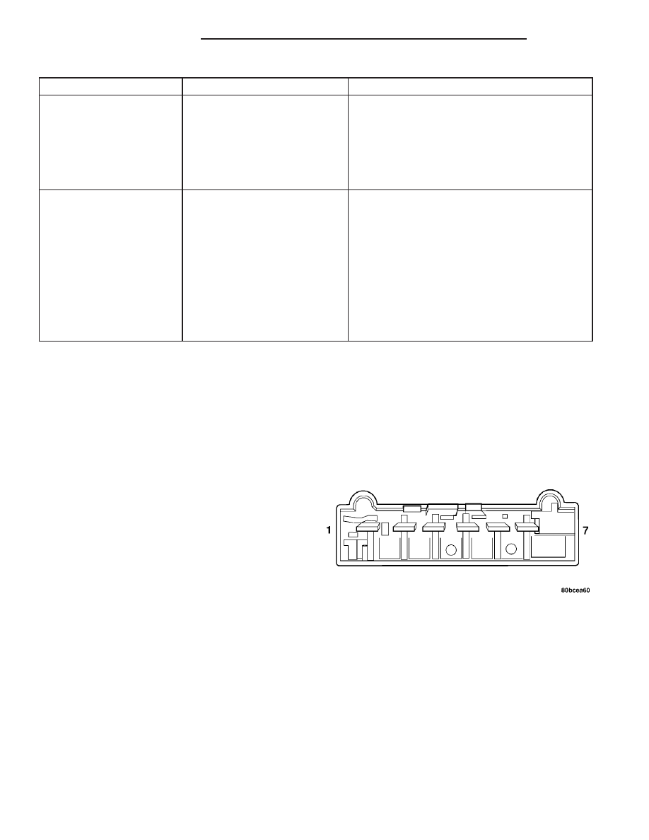
To test the wiper/washer switch, first remove the
switch (Refer to 8 - ELECTRICAL/WIPERS/WASH-
ERS/WIPER/WASHER SWITCH - REMOVAL). Then
refer to the WIPER/WASHER SWITCH CONTINU-
ITY TEST and (Fig. 12).
Fig. 12 WINDSHIELD WIPER/WASHER SWITCH
CONNECTOR (C)
8R - 10
WIPERS/WASHERS
PL/SRT-4
WIPER MOTOR (Continued)