Dodge Neon / Neon SRT-4. Manual - part 104
REMOVAL
(1) Disconnect and isolate the battery negative
cable.
(2) Using a trim stick (special tool #C-4755) or
equivalent, gently pry up on window switch bezel
and remove from door trim panel.
(3) Disconnect wire connector from switch.
(4) Remove two switch retaining screws.
INSTALLATION
(1) Install the retaining screws.
(2) Reconnect the wire connector to the switch.
(3) Insert switch into door trim panel.
(4) Connect the battery negative cable.
POWER FOLDAWAY MIRROR
DIAGNOSIS AND TESTING - POWER
FOLD-AWAY MIRROR - EXPORT
The following test is intended to test the fold-away
mirror circuits up to the power fold-away mirror.
NOTE: Battery must be fully charged prior to per-
forming this test.
(1) Remove the appropriate door trim panel retain-
ing fasteners.
(2) Remove power mirror electrical connector push
pin from inner door panel.
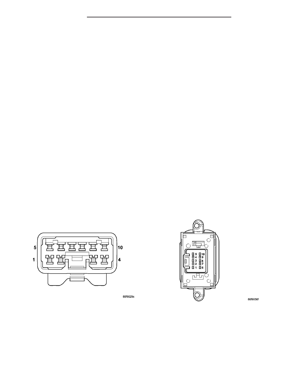
(3) Disconnect mirror electrical connector and posi-
tion as shown (Fig. 2).
(4) Depress the mirror “fold”switch and using a
voltmeter check pin # 7 for 12v. If battery voltage is
not present check wiring and or fuse for open. Refer
to Wiring Diagrams for a complete schematic of the
mirror fold-away system.
(5) Depress the mirror “unfold”switch and using a
voltmeter check pin # 4 for 12v. If battery voltage is
not present check wiring and or fuse for open. Refer
to Wiring Diagrams for a complete schematic of the
mirror fold-away system.
(6) Check for ground at pin # 3. If ground is not
present, check wiring for open. Refer to Wiring Dia-
grams for a complete schematic of the mirror fold-
away system.
(7) If the test above concluded that 12v is present
at pin # 7 and pin # 4, and a good ground is present,
the system up to the mirror is functioning properly. If
after reconnecting the power folding mirror to the
door wiring harness the mirrors do not fold/unfold,
replace the side view mirror assembly.
POWER FOLDAWAY MIRROR
SWITCH
DIAGNOSIS AND TESTING - POWER
FOLDAWAY MIRROR SWITCH - EXPORT
The following test is designed to be used only on
vehicles equipped with power fold-away side view
mirrors.
(1) Remove power mirror switch from mounting
position (Refer to 8 - ELECTRICAL/POWER MIR-
RORS/POWER FOLDAWAY MIRROR SWITCH -
REMOVAL).
(2) Using an ohmmeter, test for continuity between
the terminals of the switch as shown in the tables
below (Fig. 3).
NOTE: When testing using the chart below be cer-
tain to read the chart correctly. Example - When
testing left mirror “DOWN
↓
”, pins 1, 9, 10 will show
continuity to each other, and pins 3, 4, 5 will show
continuity to each other.
Fig. 2 POWER MIRROR ELECTRICAL CONNECTOR
FROM DOOR HARNESS
Fig. 3 POWER FOLD-AWAY MIRROR SWITCH
8N - 10
POWER MIRRORS
PL/SRT-4
POWER MIRROR SWITCH (Continued)