Dodge Neon / Neon SRT-4. Manual - part 103


  Index      Dodge     Dodge Neon / Neon SRT-4 - service repair manual 2005 year


Search            


Content   ..  101  102  103  104   ..


Dodge Neon / Neon SRT-4. Manual - part 103


DRB lll

PROGRAMMING

When using the DRB III

t scan tool, select:

(1) “Theft Alarm”
(2) “VTSS”
(3) “Miscellaneous”
and then the desired function.

CUSTOMER PROGRAMMING

For a customer to be able to program RKE trans-

mitters themselves, at least one RKE transmitter
must be programmed already. This procedure is to
add additional transmitters. If all transmitters are
lost, the DRB III

t scan tool must be used to program

the new transmitters.

(1) Insert the key into the ignition switch, and

turn the ignition switch to the RUN position without
starting the vehicle (allow chimes to stop).

(2) Using the RKE transmitter programmed to the

RKE module, press and continuously hold down the
UNLOCK button for 4-10 seconds.

(3) Within the 4-10 second time range, continue to

hold the UNLOCK button and press the PANIC but-
ton. Both buttons may then be released. Upon the
PANIC button being depressed, the message for cus-
tomer programming mode will be transmitted to the
RKE module.

(4) A chime will be heard to verify that the cus-

tomer programming mode has been entered (allow 3
seconds to hear chimes).

(5) Press and release any button on each transmit-

ter that is to be programmed to the RKE module,
including any transmitters which were previously
programmed to the RKE module (with a maximum of
four possible). After each transmitter is successfully
programmed, a chime will be heard to verify that
successful

programming

of

the

transmitter

has

occurred.

(6) After thirty seconds, or upon the ignition

switch being turned OFF, the RKE module will exit
programming mode.

POWER LOCK SWITCH

DIAGNOSIS AND TESTING - POWER LOCK
SWITCH

(1) Remove the switch from its mounting location,

and disconnect from vehicle wiring harness. (Refer to
8 - ELECTRICAL/POWER LOCKS/POWER LOCK
SWITCH - REMOVAL).

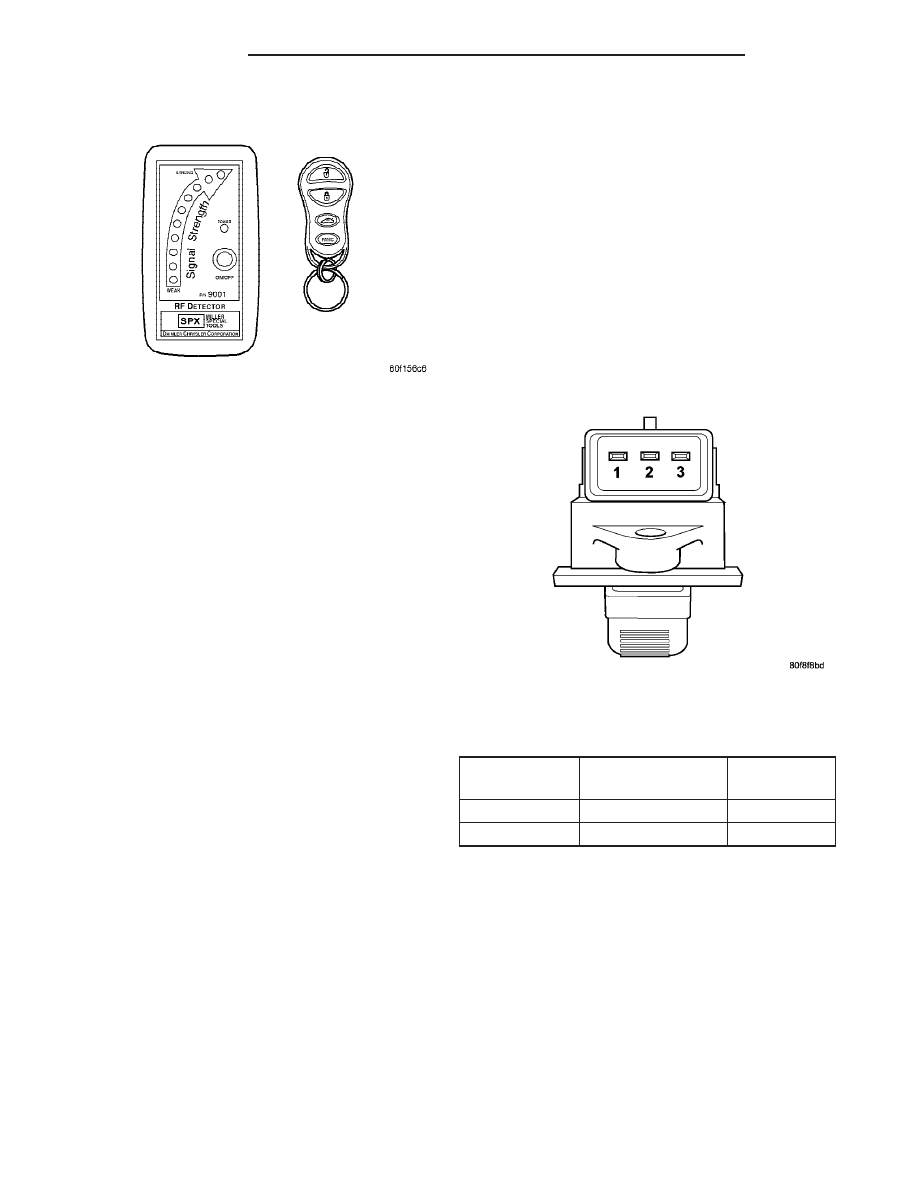
(2) Using an ohmmeter, refer to the resistance

table to determine if switch resistance is correct in
the Lock and Unlock switch positions (Fig. 3).

DOOR LOCK SWITCH RESISTANCE TABLE

SWITCH

POSITION

CONTINUITY

BETWEEN

RESISTANCE

LOCK

2 AND 3

1000 OHMS

UNLOCK

2 AND 3

249 OHMS

REMOVAL

(1) Disconnect and isolate the battery negative

cable.

(2) Remove front door trim panel. (Refer to 23 -

BODY/DOORS - REAR/TRIM PANEL - REMOVAL).

(3) Disconnect wire connector.
(4) Remove two attaching screws.
(5) Remove the switch from the door panel.

INSTALLATION

(1) Install the switch to the door panel.
(2) Install the two attaching screws.
(3) Connect the one wire connector.

Fig. 2 RKE TRANSMITTER DIAGNOSIS

Fig. 3 POWER LOCK SWITCH

8N - 6

POWER LOCKS

PL/SRT-4

REMOTE KEYLESS ENTRY TRANSMITTER (Continued)

(4) Install the front door trim panel. (Refer to 23 -

BODY/DOORS - REAR/TRIM PANEL - INSTALLA-
TION).

(5) Connect the battery negative cable.

REMOTE KEYLESS ENTRY
MODULE

DIAGNOSIS AND TESTING - REMOTE KEYLESS
ENTRY MODULE

For procedures on diagnosing and testing the RKE

Module’s RKE functions, refer to the proper Body
Diagnostic Procedures manual.

REMOVAL

(1) Disconnect and isolate the battery negative

cable.

(2) Remove the instrument panel top cover. (Refer

to 23 - BODY/INSTRUMENT PANEL/INSTRUMENT
PANEL TOP COVER - REMOVAL).

(3) Remove the two screws holding the RKE mod-

ule to the instrument panel assembly (Fig. 4).

(4) Slide locking tab of the wiring connector side-

ways to unlock tab, and remove connector from RKE
module.

(5) Remove RKE module from vehicle.

NOTE: When replacing a faulty RKE Module, the
replacement module must be configured with the
DRB lll

T

scan tool for proper operation. Addition-

ally, all transmitters must be reprogrammed to the
new RKE module.

INSTALLATION

NOTE: When replacing a faulty RKE Module, the
replacement module must be configured with the
DRB lll

T

scan tool for proper operation. Addition-

ally, all transmitters must be reprogrammed to the
new RKE module.

(1) Install the RKE module into the vehicle.
(2) Connect the RKE wiring connector.
(3) Install the two screws holding the RKE module

to the instrument panel assembly.

(4) Install the instrument panel top cover (Refer to

23 - BODY/INSTRUMENT PANEL/INSTRUMENT
PANEL TOP COVER - INSTALLATION).

(5) Connect the battery negative cable.

Fig. 4 RKE MODULE LOCATION

1 - RKE MODULE

PL/SRT-4

POWER LOCKS

8N - 7

POWER LOCK SWITCH (Continued)

POWER MIRRORS

TABLE OF CONTENTS

page

page

POWER MIRRORS

DESCRIPTION

. . . . . . . . . . . . . . . . . . . . . . . . . . 8

OPERATION

. . . . . . . . . . . . . . . . . . . . . . . . . . . . 8

DIAGNOSIS AND TESTING - POWER

MIRRORS

. . . . . . . . . . . . . . . . . . . . . . . . . . . . 8

POWER MIRROR SWITCH

DIAGNOSIS AND TESTING - POWER MIRROR

SWITCH

. . . . . . . . . . . . . . . . . . . . . . . . . . . . . 9

REMOVAL

. . . . . . . . . . . . . . . . . . . . . . . . . . . . . 10

INSTALLATION

. . . . . . . . . . . . . . . . . . . . . . . . . 10

POWER FOLDAWAY MIRROR

DIAGNOSIS AND TESTING - POWER

FOLD-AWAY MIRROR - EXPORT

. . . . . . . . . . 10

POWER FOLDAWAY MIRROR SWITCH

DIAGNOSIS AND TESTING - POWER

FOLDAWAY MIRROR SWITCH - EXPORT

. . . 10

SIDEVIEW MIRROR

REMOVAL

. . . . . . . . . . . . . . . . . . . . . . . . . . . . . 11

POWER MIRRORS

DESCRIPTION

The available power operated sideview mirrors

allow the driver to adjust both outside mirrors elec-
trically from the drivers seat by operating a switch
on the driver side front door trim panel.

Some vehicles are equipped with Power Fold-Away

Side View Mirrors. This feature allows both the
driver and passenger side view mirrors to fold
inward (retract) on demand. This feature is con-
trolled by a additional switch located on the power
mirror switch.

The fold-away side view mirror is attached to the

vehicle’s door in the same manner as mirrors without
the fold-away option. The fold-away mirrors unique
option is the internal motor which allows the mirrors
to fold inward on demand. The fold-away mirror
motor is not serviceable separately and if a motor is
found to be faulty the entire side view mirror must
be replaced.

OPERATION

The push button rocker switch uses L (left) and R

(right) for mirror selection and a button to push for
the desired direction of mirror movement.

When the mirror retract switch (if equipped) is

depressed, both of the side view mirrors will fold
inward, Thus making the overall width of the vehicle
the smallest possible. This can be helpful were park-
ing space is a absolute minimum.

The power mirrors receive ignition current through

fuses in the fuse block, and will only operate when
the ignition switch is in the Run position.

DIAGNOSIS AND TESTING - POWER MIRRORS

WIRING VOLTAGE TEST

The following wiring test determines whether or

not voltage is continuous through the body harness
to switch.

Refer to the appropriate wiring information. The

wiring information includes wiring diagrams, proper
wire and connector repair procedures, details of wire
harness routing and retention, connector pin-out
information and location views for the various wire
harness connectors, splices and grounds.

(1) Remove the power mirror switch.
(2) Disconnect wire connector from back of power

mirror switch.

(3) Switch ignition to the RUN position.
(4) Connect the clip end of a 12 volt test light to

Pin 4 in the harness connector at the mirror switch.
Touch the test light probe to Pin 3, then Pin 10.

If the test light illuminates at both pins, the wiring

circuit between the battery and switch is OK.

If the lamp does not illuminate, first check fuse 7

and fuse 1 in the Fuse Block. If fuses are OK, then
check for broken wire(s).

POWER MIRROR MOTOR TEST

If the power mirror switch is receiving proper cur-

rent and ground and mirrors do not operate, proceed
with power mirror motor test. Refer to the appropri-
ate

wiring

information.

The

wiring

information

includes wiring diagrams, proper wire and connector
repair procedures, details of wire harness routing
and retention, connector pin-out information and
location views for the various wire harness connec-
tors, splices and grounds.

(1) Remove front door trim panel to gain access to

power mirror wire connector.

8N - 8

POWER MIRRORS

PL/SRT-4

(2) Disconnect wire harness connector to power

mirror switch.

(3) Using two jumper wires:
• Connect one to a 12 volt source

• Connect the other to a good body ground

• Refer to the Mirror Motor Test Chart for proper

wire connections at the switch connector.

MIRROR MOTOR TEST CHART

12 VOLTS

GROUND

MIRROR REACTION

SWITCH CONNECTOR

RIGHT

LEFT

PIN 2

PIN 6

-

UP

PIN 6

PIN 1

-

LEFT

PIN 6

PIN 2

-

DOWN

PIN 1

PIN 6

-

RIGHT

PIN 9

PIN 6

UP

-

PIN 6

PIN 10

LEFT

-

PIN 6

PIN 9

DOWN

-

PIN 10

PIN 6

RIGHT

-

(4) If results shown in table are not obtained,

check for open or shorted circuit. Replace mirror
assembly as necessary.

POWER MIRROR SWITCH

DIAGNOSIS AND TESTING - POWER MIRROR
SWITCH

(1) Remove power mirror switch.
(2) Disconnect

wiring

harness

connector

from

switch and position as shown (Fig. 1).

(3) Using a ohmmeter, test for continuity between

the terminals of the switch.

(4) If results shown in the table are not obtained,

replace the switch.

POWER MIRROR SWITCH TABLE

SWITCH POSITION

CONTINUITY BETWEEN

MIRROR SELECT SWITCH IN

9

LEFT

9

POSITION

UP

4 AND 5
4 AND 8
5 AND 8
6 AND 9

6 AND 10
9 AND 10

DOWN

4 AND 5
4 AND 6
5 AND 6
8 AND 9

8 AND 10
9 AND 10

LEFT

4 AND 5
4 AND 8
5 AND 8
7 AND 9

7 AND 10
9 AND 10

RIGHT

4 AND 5
4 AND 7
5 AND 7
8 AND 9

8 AND 10
9 AND 10

MIRROR SELECT SWITCH IN

9

RIGHT

9

POSITION

UP

1 AND 9

1 AND 10

4 AND 5
4 AND 8
5 AND 8

9 AND 10

DOWN

1 AND 4
1 AND 5
4 AND 5

9 AND 10

LEFT

2 AND 9

2 AND 10

4 AND 5
4 AND 8
5 AND 8

9 AND 10

RIGHT

2 AND 4
2 AND 5
4 AND 5
8 AND 9

8 AND 10
9 AND 10

Fig. 1 POWER MIRROR SWITCH

PL/SRT-4

POWER MIRRORS

8N - 9

POWER MIRRORS (Continued)


Content   ..  101  102  103  104   ..