Dodge Neon / Neon SRT-4. Manual - part 74


  Index      Dodge     Dodge Neon / Neon SRT-4 - service repair manual 2005 year


Search            


Content   ..  72  73  74  75   ..


Dodge Neon / Neon SRT-4. Manual - part 74


OPERATION - DATA BUS COMMUNICATION
RECEIVE - PCM INPUT

The PCM uses the SCI communication bus to pre-

form engine diagnostics and flash operations. The
transmission side of the PCM uses the SCI commu-
nication bus to flash new software. However, diagnos-
tics is performed via the vehicles J1850 bus for the
transmission side of the PCM.

OPERATION - IGNITION SENSE - PCM INPUT

The ignition sense input informs the Powertrain

Control Module (PCM) that the ignition switch is in
the crank or run position.

OPERATION - PCM GROUND

Ground is provided through multiple pins of the

PCM connector. Depending on the vehicle there may
be as many as two different ground pins. There are
power grounds and sensor grounds.

The power grounds are used to control the ground

side relays, solenoids, ignition coil or injectors. The
signal ground is used for any input that uses sensor
return for ground, and the ground side of any inter-
nal processing component.

The PCM case is shielded to prevent RFI and EMI.

The PCM case is grounded and must be firmly
attached to a good, clean body ground.

Internally all grounds are connected together, how-

ever there is noise suppression on the sensor ground.
For EMI and RFI protection the housing and cover
are also grounded separately from the ground pins.

OPERATION

OPERATION

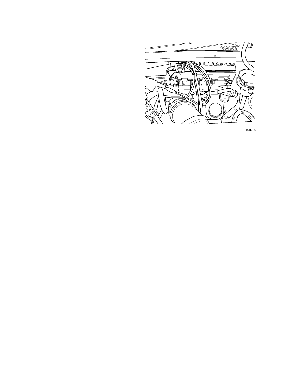
The PCM receives input signals from various

switches and sensors that are referred to as PCM
Inputs. Based on these inputs, the PCM adjusts var-
ious engine, transmission, and vehicle operations
through devices that are referred to as PCM Outputs
(Fig. 5).

NOTE: PCM Inputs:

• Air Conditioning Controls

• Ambient Air temperature Sensor

• ASD Sense

• Baro/Tip (Turbo)

• Battery Voltage

• Battery Temperature Sensor

• Brake Switch

• Camshaft Position Sensor

• Clutch Upstop Switch

• Clutch Interlock

• Crankshaft Position Sensor

• Engine Coolant Temperature Sensor

• Fuel Level Sensor (Bus message)

• Ignition Switch

• Intake Air Temperature Sensor

• J1850

• Knock Sensor (2.0, 2.4L)

• Natural Vacuum Leak Detection (NVLD)

• Manifold Absolute Pressure (MAP) Sensor

• Oil Pressure Switch

• Oxygen Sensors

• Power Steering Pressure Switch

• SCI Receive

• Speed Control Switches

• Throttle Position Sensor

• Transmission Control Relay (Switched B+)

• Transmission Input Shaft Speed Sensor

• Transmission Output Shaft Speed Sensor

• Transmission Pressure Switches (L/R, 2/4, OD)

• Transmission Range Sensor (TRS)

• Transmission Oil Temperature Sensor (Integral

to TRS)

• Vehicle Speed Sensor (MTX-equipped models)

NOTE: PCM Outputs:

• Air Conditioning Clutch Relay

• Auto Shutdown (ASD) Relay

• Charging Indicator Lamp (Bus Message)

• SCI Transmit

• Proportional Purge Solenoid

• EGR Solenoid

• Fuel Injectors

• Fuel Pump Relay

• Generator Field

• Idle Air Control Motor (2.0/2.4L)

• Ignition Coils

Fig. 5 PCM

8E - 6

ELECTRONIC CONTROL MODULES

PL/SRT-4

POWERTRAIN CONTROL MODULE (Continued)

• J1850

• Malfunction Indicator (Check Engine) Lamp

(Bus Message)

• Oxygen Sensors Heater Controls

• Radiator Fan Relays

• Speed Control Solenoids (2.0/2.4L)

• Transmission Control Relay

• Transmission Solenoids (LR/CC, 2/4, OD, and

UD)

• Transmission PRNDL Position (to Cluster)

• Transmission Torque Reduction Request (Inter-

nal to PCM)

• Transmission Temperature (Internal to PCM and

a Bus Message)

• Vehicle Speed (Manual Transmission)
Based on inputs it receives, the PCM adjusts fuel

injector pulse width, idle speed, ignition spark
advance, ignition coil dwell and EVAP canister purge
operation. The PCM also determines the appropriate
transmission shift schedule and shift points, depend-
ing on the present operating conditions and driver
demand. The PCM regulates the cooling fan, air con-
ditioning and speed control systems. The PCM
changes generator charge rate by adjusting the gen-
erator field. The PCM also performs diagnostics.

The PCM adjusts injector pulse width (air-fuel

ratio) based on the following inputs.

• Battery voltage

• Coolant temperature

• Exhaust gas content (oxygen sensor)

• Engine speed (crankshaft position sensor)

• Intake air temperature

• Manifold absolute pressure

• Throttle position
The PCM adjusts ignition timing based on the fol-

lowing inputs.

• Coolant temperature

• Engine speed (crankshaft position sensor)

• Knock sensor

• Manifold absolute pressure

• Throttle position

• Transmission

gear

selection

(park/neutral

switch)

• Intake air temperature
The PCM also adjusts engine idle speed through

the idle air control motor based on the following
inputs.

• Air conditioning sense

• Battery voltage

• Battery temperature

• Brake switch

• Coolant temperature

• Engine speed (crankshaft position sensor)

• Engine run time

• Manifold absolute pressure

• Power steering pressure switch

• Throttle position

• Transmission

gear

selection

(park/neutral

switch)

• Vehicle distance (speed)
The Auto Shutdown (ASD) and fuel pump relays

are located in the Power Distribution Center (PDC).

The camshaft position sensor and crankshaft posi-

tion sensor signals are sent to the PCM. If the PCM
does not receive the signal within approximately 1
second of engine cranking, it deactivates the ASD
relay and fuel pump relay. When these relays are
deactivated, power is shut off from the fuel injectors,
ignition coils, oxygen sensor heating elements and
fuel pump.

The

PCM

contains

a

voltage

converter

that

changes battery voltage to a regulated 5 volts direct
current to power the camshaft position sensor, crank-
shaft position sensor, manifold absolute pressure sen-
sor, throttle position sensor, A/C pressure switch, A/C
pressure transducer, and vehicle speed sensor.

Powertrain Control Module Connectors

The PCM is an engine and transmission controller

module all in one, if the vehicle is equipped with an
automatic transmission. The PCM uses four wiring
harness connectors to receive and send engine and
transmission data. To ease assembly, the mating wir-
ing harness connector is color-coded. Each module
connector cavity has its own unique color identifica-
tion stripe located on the outside of each connector
cavity.

The PCM module utilizes four wiring harness con-

nectors as described:

• Connector Cavity A is for Power & Ground

(Black)

• Connector Cavity B is for Engine Side (Orange)

• Connector Cavity C is for Headlamp & Dash

(White)

• Connector Cavity D is for Transmission (Green)

If equipped

NOTE: Connector Cavities A, B, C, And D must be
connected prior to battery connection and ignition
key on to avoid setting erroneous controller fault
codes. It is also recommended that cavity A con-
nector is made prior to any other connectors.

TRANSMISSION CONTROL

CLUTCH VOLUME INDEX (CVI)

An important function of the PCM is to monitor

Transmission Clutch Volume Index (CVI). CVIs rep-
resent the volume of fluid needed to compress a
clutch pack.

The PCM monitors gear ratio changes by monitor-

ing the Input and Output Speed Sensors. The Input,

PL/SRT-4

ELECTRONIC CONTROL MODULES

8E - 7

POWERTRAIN CONTROL MODULE (Continued)

or Turbine Speed Sensor sends an electrical signal to
the PCM that represents input shaft rpm. The Out-
put Speed Sensor provides the PCM with output
shaft speed information.

By comparing the two inputs, the PCM can deter-

mine transaxle gear ratio. This is important to the
CVI calculation because the PCM determines CVIs
by monitoring how long it takes for a gear change to
occur (Fig. 6).

Gear ratios can be determined by using the

DRBIII

t Scan Tool and reading the Input/Output

Speed Sensor values in the “Monitors” display. Gear
ratio can be obtained by dividing the Input Speed
Sensor value by the Output Speed Sensor value.

For example, if the input shaft is rotating at 1000

rpm and the output shaft is rotating at 500 rpm,
then the PCM can determine that the gear ratio is
2:1. In direct drive (3rd gear), the gear ratio changes
to 1:1. The gear ratio changes as clutches are applied
and released. By monitoring the length of time it
takes for the gear ratio to change following a shift
request, the PCM can determine the volume of fluid
used to apply or release a friction element.

The volume of transmission fluid needed to apply

the friction elements are continuously updated for
adaptive controls. As friction material wears, the vol-
ume of fluid need to apply the element increases.

Certain mechanical problems within the clutch

assemblies (broken return springs, out of position
snap rings, excessive clutch pack clearance, improper
assembly, etc.) can cause inadequate or out-of-range
clutch volumes. Also, defective Input/Output Speed

Sensors and wiring can cause these conditions. The
following chart identifies the appropriate clutch vol-
umes and when they are monitored/updated:

CLUTCH VOLUMES

Clutch

When Updated

Proper Clutch

Volume

Shift Sequence

Oil Temperature

Throttle Angle

L/R

2-1 or 3-1 coast

downshift

> 70°

< 5°

35 to 83

2/4

1-2 shift

> 110°

5 - 54°

20 to 77

OD

2-3 shift

48 to 150

UD

4-3 or 4-2 shift

> 5°

24 to 70

TRANSMISSION SHIFT SCHEDULES

The PCM is programmed to allow it to select a

variety of shift schedules. Shift schedule selection is
dependent on the following:

• Shift lever position

• Throttle position

• Engine load

• Fluid temperature

• Software calibration level
As driving conditions change, the PCM appropri-

ately adjusts the shift schedule. Refer to the follow-

ing chart to determine the appropriate operation
expected, depending on driving conditions.

Fig. 6 Example of CVI Calculation

1 - OUTPUT SPEED SENSOR
2 - OUTPUT SHAFT
3 - CLUTCH PACK
4 - SEPARATOR PLATE
5 - FRICTION DISCS
6 - INPUT SHAFT
7 - INPUT SPEED SENSOR
8 - PISTON AND SEAL

8E - 8

ELECTRONIC CONTROL MODULES

PL/SRT-4

POWERTRAIN CONTROL MODULE (Continued)

Schedule

Condition

Expected Operation

Extreme Cold

Oil temperature at start-up below
-16° F

Park, Reverse, Neutral and 2nd
gear only (prevents shifting which
may fail a clutch with frequent
shifts)

Cold

Oil temperature at start-up above
-12° F and below 36° F

– Delayed 2-3 upshift
(approximately 22-31 mph)

– Delayed 3-4 upshift (45-53 mph)

– Early 4-3 costdown shift
(approximately 30 mph)

– Early 3-2 coastdown shift
(approximately 17 mph)

– High speed 4-2, 3-2, 2-1 kickdown
shifts are prevented

– No EMCC

Warm

Oil temperature at start-up above
36° F and below 80 degree F

– Normal operation (upshift,
kickdowns, and coastdowns)

– No EMCC

Hot

Oil temperature at start-up above
80° F

– Normal operation (upshift,
kickdowns, and coastdowns)

– Full EMCC, no PEMCC except to
engage FEMCC (except at closed
throttle at speeds above 70-83 mph)

Overheat

Oil temperature above 240° F or
engine coolant temperature above
244° F

– Delayed 2-3 upshift (25-32 mph)

– Delayed 3-4 upshift (41-48 mph)

– 3rd gear FEMCC from 30-48 mph

– 3rd gear PEMCC from 27-31 mph

Super Overheat

Oil temperature above 260° F

– All

9

Overheat

9

shift schedule

features apply

– 2nd gear PEMCC above 22 mph

– Above 22 mph the torque
converter will not unlock unless the
throttle is closed or if a wide open
throttle 2nd PEMCC to 1 kickdown
is made

OPERATION - 5 VOLT SUPPLY - PCM OUTPUT

The PCM supplies 5 volts to the following sensors:
• A/C pressure transducer

• Ambient Temperature sensor

• Battery temperature

• Camshaft Position Sensor (NGC)

• Crankshaft Position Sensor (NGC)

• Electronic Throttle Control (1.6L)

• Engine coolant temperature sensor

• Inlet Air Temperature Sensor

• Knock sensor

• Linear EGR solenoid (if equipped)

• Manifold absolute pressure sensor

• Oil Pressure Switch

• Pedal Position Sensor (1.6L)

• Throttle position sensor

• Vehicle Speed Sensor

PL/SRT-4

ELECTRONIC CONTROL MODULES

8E - 9

POWERTRAIN CONTROL MODULE (Continued)


Content   ..  72  73  74  75   ..