Dodge Neon / Neon SRT-4. Manual - part 66
REMOVAL
(1) Drain the cooling system (Refer to 7 - COOL-
ING/ENGINE - STANDARD PROCEDURE).
(2) Detach power cord plug from heater (Fig. 8).
(3) Loosen screw in center of heater. Remove
heater assembly (Fig. 8).
INSTALLATION
(1) Thoroughly clean core hole and heater seat.
(2) Insert heater assembly with element loop posi-
tioned upward (Fig. 8).
(3) With
heater
seated,
tighten
center
screw
securely to assure a positive seal.
(4) Connect power cord to block heater (Fig. 8).
(5) Fill the cooling system (Refer to 7 - COOLING/
ENGINE - STANDARD PROCEDURE).
ENGINE COOLANT TEMP
SENSOR
DESCRIPTION
The engine coolant temperature (ECT) sensor
threads into the rear of the cylinder head, next to the
camshaft position sensor (Fig. 9). New sensors have
sealant applied to the threads.
The ECT Sensor is a Negative Thermal Coefficient
(NTC) Sensor. The resistance of the ECT Sensor
changes as coolant temperature changes. This results
in different input voltages to the PCM. The PCM also
uses the ECT Sensor input to operate the radiator
cooling fan(s), and send a message over the PCI bus
to the instrument cluster for temperature gauge
operation.
OPERATION
The ECT sensor provides an input to the PCM. As
temperature
increases,
resistance
of
the
sensor
decreases. As coolant temperature varies, the ECT
sensor resistance changes resulting in a different
voltage value at the PCM ECT sensor signal circuit.
The ECT sensor provides input for various PCM
operations. The PCM uses the input to control air-
fuel mixture, timing, and radiator fan on/off times.
The PCM uses ECT sensor input to send messages
over the PCI bus for temperature gauge operation.
REMOVAL
(1) With the engine cold, drain coolant until level
drops below cylinder head (Refer to 7 - COOLING/
ENGINE - STANDARD PROCEDURE).
(2) Disconnect coolant sensor electrical connector
(Fig. 9).
(3) Remove coolant sensor.
INSTALLATION
(1) Install coolant sensor. Tighten sensor to 18
N·m (165 in. lbs.) torque.
(2) Attach electrical connector to sensor (Fig. 9).
(3) Fill cooling system (Refer to 7 - COOLING/EN-
GINE - STANDARD PROCEDURE).
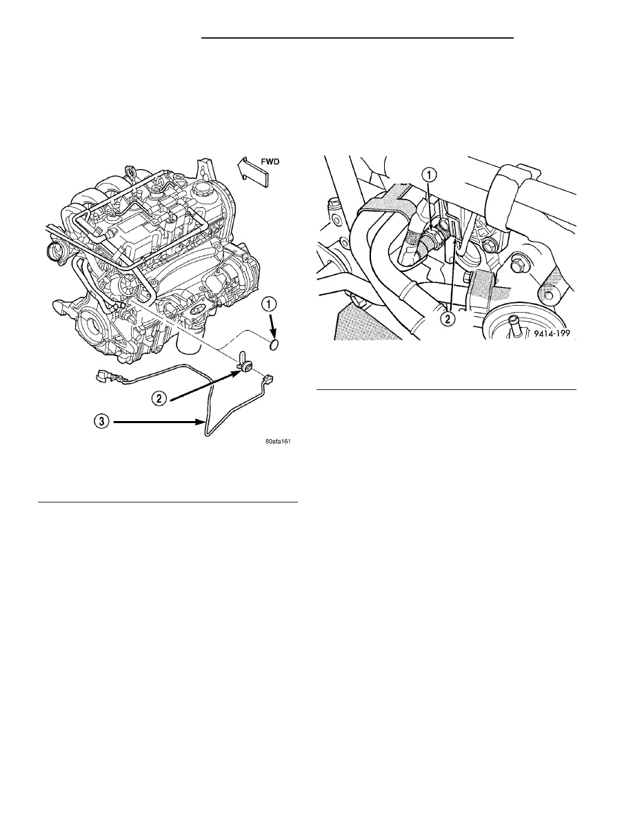
Fig. 8 Engine Block Heater
1 - CORE PLUG
2 - BLOCK HEATER
3 - POWER CORD
Fig. 9 Engine Coolant Temperature Sensor—SOHC
1 - ENGINE COOLANT TEMPERATURE SENSOR
2 - CAMSHAFT POSITION SENSOR
7 - 22
ENGINE - 2.0L SOHC
PL/SRT-4
ENGINE BLOCK HEATER (Continued)