Dodge Neon / Neon SRT-4. Manual - part 55
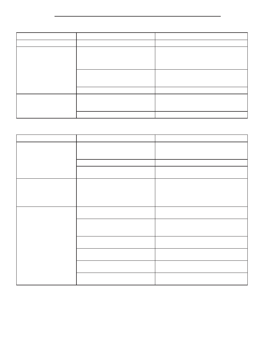
CONDITION
POSSIBLE CAUSES
CORRECTION
Road splash, water entering housing
Seal housing. Inspect clutch assembly.
CLUTCH IS RUNNING
PARTIALLY DISENGAGED
Release bearing sticking or binding,
does not return to normal running
position.
Verify that bearing is actually binding. Then,
replace bearing and transmission front
bearing retainer if sleeve surface is
damaged.
Clutch master cylinder pushrod not
adjusted properly, causing high
preload (LHD Models).
Verify that pushrod adjustment is correct.
Slave cylinder binding
Replace slave cylinder.
CLUTCH DISC FACINGS
HAVE FRACTURED INTO
SMALL PIECES
Leak at rear main or transaxle input
shaft seal
Replace seal. Replace clutch assembly.
Excessive heat from slippage
Replace clutch assembly
SERVICE DIAGNOSIS - IMPROPER CLUTCH RELEASE
CONDITION
POSSIBLE CAUSES
CORRECTION
CLUTCH DISC BINDS ON
INPUT SHAFT SPLINES
Clutch disc hub splines damaged
during installation
Clean, smooth, and lubricate disc and shaft
splines. Replace clutch assembly and/or
input shaft if splines are severely damaged.
Input shaft splines rough, damaged.
Clean input shaft splines. Then lube.
Corrosion or rust formations on
splines of input shaft and disc
Clean input shaft splines and disc splines,
then lube
CLUTCH DISC RUSTED
TO FLYWHEEL AND/OR
PRESSURE PLATE
Occurs in vehicles stored or not
driven for extended period of time.
Also occurs after steam cleaning if
vehicle is not used for extended
period.
Replace clutch assembly
CLUTCH WILL NOT
DISENGAGE PROPERLY
Disc bent, distorted during transaxle
installation
Replace clutch assembly
Clutch cover diaphragm spring
damaged during transaxle
installation
Replace clutch assembly
Release lever bent, loose, or
damaged
Replace release lever if worn or damaged
Clutch master cylinder or slave
cylinder leaking
Check and replace master and/or slave
cylinder
Master cylinder adjustable pushrod
loose or damaged (LHD models)
Inspect. Tighten adjustment fastener or
replace master cylinder
Master cylinder push rod not
retained to pedal pin.
Inspect pushrod and bushing. Replace as
necessary
6 - 4
CLUTCH
PL/SRT-4
CLUTCH (Continued)