Dodge Neon / Neon SRT-4. Manual - part 53
REMOVAL - ICU
NOTE: If servicing the controller antilock brake
(CAB) only, the CAB can be serviced with the ICU
mounted in the vehicle. (Refer to 8 - ELECTRICAL/
ELECTRONIC CONTROL MODULES/CONTROLLER
ANTILOCK BRAKE - REMOVAL)
NOTE: Before proceeding, (Refer to 5 - BRAKES -
WARNING).
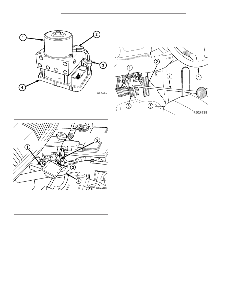
(1) Using a brake pedal holder, depress the brake
pedal past its first one inch of travel and hold it in
this position (Fig. 16). This will isolate the master
cylinder from the brake hydraulic system and will
not allow the brake fluid to drain out of the master
cylinder reservoir.
(2) Disconnect negative (ground) cable from the
battery and isolate the cable.
(3) Disconnect the positive cable from the battery,
then remove the battery from the battery tray. There
is one nut securing the clamp on the backside of the
battery holding it in place.
(4) Remove the one nut and one bolt securing the
air cleaner box in place, then disconnect the wiring
harness connector at the air inlet sensor.
(5) Lift the air cleaner box upward enough to clear
its grommeted alignment post (Fig. 17), then move
the air cleaner box forward just enough to access the
battery tray mounting bolts.
(6) Remove the 2 bolts, then the 2 nuts mounting
the battery tray to its bracket (Fig. 17). Remove the
battery tray.
(7) Disconnect the primary and secondary brake
tubes from the master cylinder (Fig. 18). Install
plugs in the master cylinder outlet ports.
(8) Disconnect the 24-way connector from the con-
troller antilock brake (CAB) mounted on the inte-
grated control unit (ICU) and move it out of the way.
The connector is disconnected by pulling outward on
the connector lock (Fig. 19). This will unlock and
raise the 24-way connector out of the socket on the
CAB.
(9) Tag the brake tubes coming from the master
cylinder as primary and secondary (Fig. 18). This is
Fig. 14 Integrated Control Unit (ICU)
1 - PUMP/MOTOR
2 - HCU
3 - PUMP/MOTOR WIRING CONNECTOR
4 - CAB
Fig. 15 Master Cylinder And ICU
1 - PRIMARY BRAKE TUBE
2 - MASTER CYLINDER
3 - SECONDARY BRAKE TUBE
4 - ABS ICU
Fig. 16 Brake Pedal Holder
1 - CLUTCH PEDAL (IF EQUIPPED WITH MANUAL TRANSAXLE)
2 - THROTTLE PEDAL
3 - BRAKE PEDAL HOLDING TOOL
4 - STEERING WHEEL
5 - DRIVER’S SEAT
6 - BRAKE PEDAL
5 - 94
BRAKES - ABS
PL/SRT-4
ICU - INTEGRATED CONTROL UNIT (Continued)