Dodge Neon / Neon SRT-4. Manual - part 36


  Index      Dodge     Dodge Neon / Neon SRT-4 - service repair manual 2005 year


Search            


Content   ..  34  35  36  37   ..


Dodge Neon / Neon SRT-4. Manual - part 36


Brake shoes with lack of contact at the toe or heel

of the brake shoe lining may be improperly ground.

Clean and inspect the brake support plate and

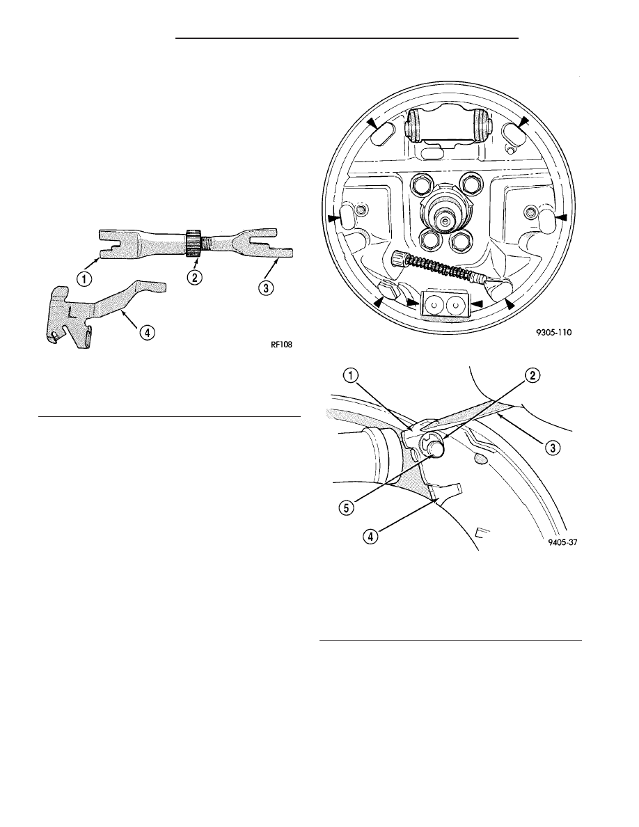
shoe adjuster screw. Apply a thin coat of Mopar
Multi-Purpose Lubricant or equivalent to the threads
of the self-adjuster (Fig. 40). Replace the adjuster
screw if it is corroded.

NOTE: Adjuster screws are different side-to-side.
Left side adjuster screws have left-hand threads
and right side adjuster screws have right-handed
threads.

If the old brake shoe return or hold down springs

have overheated or are damaged, replace them. Over-
heating indications are paint discoloration or dis-
torted end coils.

INSTALLATION - DRUM BRAKE SHOES (REAR)

NOTE: Before proceeding with this procedure,
(Refer to 5 - BRAKES - WARNING).

(1) Begin on one side of the vehicle.
(2) Lubricate the eight shoe contact areas on the

support plate and anchor using Mopar Multi-Purpose
Lubricant or equivalent (Fig. 41).

(3) Assemble the front and rear brake shoe assem-

bly, automatic adjuster screw, and upper return
spring before installation on the vehicle.

(4)

Install the pre-assembled brake shoes, auto-

matic adjuster screw and upper return spring on the
brake support plate (Fig. 39).

(5) Install the wave washer on the pin of park

brake lever.

(6) Install the pin on the parking brake lever into

hole in rear brake shoe assembly (Fig. 42).

(7) Install both brake shoe-to-brake support plate

hold down pins and clips (Fig. 36).

(8) Install the lower brake shoe-to-anchor plate

return spring (Fig. 37).

(9) Install the automatic adjustment lever on the

leading brake shoe (Fig. 35).

(10) Install the automatic adjustment lever-to-

brake shoe spring (Fig. 34).

(11) Adjust the brake shoes out until the drum

lightly drags on the shoes when it is installed. Do not
over-adjust the brakes.

(12) Install the brake drum (Fig. 33).
(13) Repeat the above procedure to the rear brakes

on the other side of the vehicle.

Fig. 40 Adjuster Screw And Lever (Typical)

1 - OUTBOARD FORWARD
2 - SELF ADJUSTER
3 - OUTBOARD REAR
4 - SELF ADJUSTER LEVER

Fig. 41 Shoe Contact Areas on Support Plate

Fig. 42 Parking Brake Lever Pin Retaining Clip

Installation

1 - BRAKE SHOE ASSEMBLY
2 - RETAINING CLIP
3 - SCREWDRIVER
4 - PARK BRAKE LEVER
5 - PARK BRAKE LEVER PIN

5 - 26

BRAKES - BASE

PL/SRT-4

BRAKE PADS/SHOES - REAR DRUM (Continued)

(14) Install the tire and wheel assemblies (Refer to

22 - TIRES/WHEELS - INSTALLATION). Tighten
the wheel mounting nuts to a torque of 135 N·m (100
ft. lbs.).

(15) Adjust the rear brake shoes. (Refer to 5 -

BRAKES/HYDRAULIC/MECHANICAL/BRAKE
PADS/SHOES - ADJUSTMENTS).

(16) Lower the vehicle.
(17) Road test vehicle stopping in both the forward

and reverse directions. The automatic adjuster will
continue to adjust the brakes during the road test of
the vehicle.

ADJUSTMENTS

ADJUSTMENT - DRUM BRAKE SHOES

(1) Verify the parking brake lever is in the fully

released position.

(2) Raise the vehicle. (Refer to LUBRICATION &

MAINTENANCE/HOISTING - STANDARD PROCE-
DURE).

(3) Remove the rear brake adjusting hole rubber

plug from the rear brake shoe support plate (Fig. 43).

(4) Insert a brake adjustment tool, or a screw-

driver, through the adjusting hole in support plate
and against the star wheel of the adjuster screw.
Move the handle of tool downward to adjust the
brake drag. Rotate the tire and wheel assembly while
adjusting the adjuster screw. Continue to adjust the
shoes until a slight drag is noticed when the tire and
wheel assembly is rotated.

NOTE: In the event the brake shoes are over-ad-
justed, the adjuster can be backed off using the fol-
lowing step. If not, proceed to step 6.

(5) If the shoes are in the over-adjusted position,

insert a thin screwdriver into brake adjusting hole
and push back the adjusting lever out of engagement
with star wheel (Fig. 44). Take care not to bend the
adjusting lever. While holding the adjusting lever out
of engagement with star wheel, back off the star
wheel until the tire and wheel assembly is free to
turn without dragging. Repeat the adjustment proce-
dure.

(6) Install adjusting hole rubber plug (Fig. 43).
(7) Repeat the above adjustment procedure to the

other side brakes.

(8) Apply and release the park brake lever one

time after the adjustment process is completed so the
parking brakes can readjust themselves to the new
brake shoe adjustment.

DISC BRAKE CALIPER -
FRONT

REMOVAL

NOTE: Before proceeding, (Refer to 5 - BRAKES -
WARNING).

(1) Using a brake pedal holding tool as shown (Fig.

45), depress the brake pedal past its first one inch of
travel and hold it in this position. This will isolate
the master cylinder from the brake hydraulic system
and will not allow the brake fluid to drain out of the
master cylinder reservoir when the lines are opened.

(2) Raise the vehicle. (Refer to LUBRICATION &

MAINTENANCE/HOISTING - STANDARD PROCE-
DURE).

Fig. 43 Rear Brake Adjusting Hole Plug

1 - REAR BRAKE SUPPORT PLATE
2 - REAR STRUT
3 - BRAKE ADJUSTING HOLE PLUG

Fig. 44 Backing Off Brake Adjuster

1 - MEDIUM SCREWDRIVER
2 - BRAKE ADJUSTING HOLE
3 - THIN SCREWDRIVER OR WELDING ROD

PL/SRT-4

BRAKES - BASE

5 - 27

BRAKE PADS/SHOES - REAR DRUM (Continued)

(3) Remove the front tire and wheel assembly

(Refer to 22 - TIRES/WHEELS - REMOVAL).

(4) Remove the banjo bolt connecting the brake

hose to the brake caliper (Fig. 46). There are two
washers (one on each side of the flex hose fitting)
that will come off with the banjo bolt. Discard these
washers. 
Replace them with new ones.

NOTE: In some cases, it may be necessary to
retract the caliper piston in its bore a small amount
in order to provide sufficient clearance between the
shoes and the rotor to easily remove the caliper
from the knuckle. This can usually be accomplished
before the guide pin bolts are removed, by grasping

the rear of the caliper and pulling outward working
with the guide pins, thus retracting the piston.
Never push on the piston directly as it may get
damaged.

(5) Remove the two brake caliper to steering

knuckle guide pin bolts (Fig. 47).

(6) Remove the disc brake caliper from the steer-

ing knuckle. The caliper is removed by first tipping
either the top (right side caliper) or bottom (left side
caliper) of the caliper away from the brake rotor,
then pulling the caliper off the opposite end’s caliper
slide abutment (on the knuckle) and brake rotor.

DISASSEMBLY

DISASSEMBLY (GUIDE PIN BUSHINGS)

Before disassembling the brake caliper, clean and

inspect it. (Refer to 5 - BRAKES/HYDRAULIC/ME-
CHANICAL/DISC BRAKE CALIPERS - INSPEC-
TION).

(1) With one hand, push the guide pin bushing

sleeve towards the back of the caliper, and at the
same time, pull the sleeve out the back of the caliper
and bushing (Fig. 48).

(2) Using your fingers, collapse one side of the rub-

ber guide pin bushing. Pull the guide pin bushing out
the other side of the brake caliper mounting boss
(Fig. 49).

Fig. 45 Brake Pedal Holding Tool

1 - CLUTCH PEDAL (IF EQUIPPED WITH MANUAL TRANSAXLE)
2 - THROTTLE PEDAL
3 - BRAKE PEDAL HOLDING TOOL
4 - STEERING WHEEL
5 - DRIVER’S SEAT
6 - BRAKE PEDAL

Fig. 46 Brake Hose Mounting To Caliper

1 - CALIPER
2 - HOSE
3 - BOLT

Fig. 47 Caliper Mounting

1 - RETAINER CLIP
2 - BRAKE ROTOR
3 - HUB
4 - GUIDE PIN BOLTS
5 - DISC BRAKE CALIPER

5 - 28

BRAKES - BASE

PL/SRT-4

DISC BRAKE CALIPER - FRONT (Continued)

DISASSEMBLY (PISTON AND SEAL)

Before disassembling the brake caliper, clean and

inspect it. (Refer to 5 - BRAKES/HYDRAULIC/ME-

CHANICAL/DISC BRAKE CALIPERS - INSPEC-
TION).

CALIPER PISTON REMOVAL

WARNING: UNDER NO CONDITION SHOULD HIGH
PRESSURE AIR EVER BE USED TO REMOVE A PIS-
TON FROM A CALIPER BORE. PERSONAL INJURY
COULD RESULT FROM SUCH A PRACTICE.

NOTE: The safest way to remove the piston from
the caliper bore is to use the hydraulic pressure of
the vehicle’s brake system.

(1) Following the removal procedure in DISC

BRAKE SHOES (Refer to 5 - BRAKES/HYDRAULIC/
MECHANICAL/BRAKE PADS/SHOES - REMOVAL),
remove the caliper from the brake rotor and hang the
assembly on a wire hook away from rotor and body of
the vehicle so brake fluid cannot get on these compo-
nents. Remove the brake shoes, and place a small
piece of wood between the piston and caliper fingers.

(2) Carefully depress the brake pedal to hydrauli-

cally push piston out of its bore. Once completed,
apply and hold down the brake pedal to any position
beyond the first inch of pedal travel using a brake
pedal holding tool. This will prevent the fluid in the
master cylinder reservoir from completely draining
out.

(3) Disconnect the brake fluid flex hose from the

caliper assembly and remove it from the vehicle.

CALIPER SEAL REMOVAL

CAUTION: Do not use excessive force when clamp-
ing caliper in vise. Excessive vise pressure will
cause bore distortion.

(1) To disassemble the caliper, mount it in a vise

equipped with protective jaws.

(2) Remove the piston dust boot from the caliper

and discard (Fig. 50).

NOTE: Do not use a screw driver or other metal tool
for seal removal. Using such tools can scratch the
bore or leave burrs on the seal groove edges.

(3) Using a soft tool such as a plastic trim stick,

work the piston seal out of its groove in caliper pis-
ton bore (Fig. 51). Discard the old seal.

(4) Clean the piston bore and drilled passage ways

using alcohol or a suitable solvent. Wipe it dry using
only a lint-free cloth.

Fig. 48 Removing Sleeve From Bushing

1 - CALIPER
2 - SLEEVE
3 - BUSHING

Fig. 49 Removing Bushing From Caliper

1 - CALIPER
2 - BUSHING

PL/SRT-4

BRAKES - BASE

5 - 29

DISC BRAKE CALIPER - FRONT (Continued)


Content   ..  34  35  36  37   ..