Dodge Neon / Neon SRT-4. Manual - part 26


  Index      Dodge     Dodge Neon / Neon SRT-4 - service repair manual 2005 year


Search            


Content   ..  24  25  26  27   ..


Dodge Neon / Neon SRT-4. Manual - part 26


(11) Remove halfshaft(s) (Fig. 17). Left halfshaft:

While applying outward pressure on joint by hand,
dislodge inner tripod joint from differential side gear
by striking outward with a punch. When removing
tripod joint and halfshaft, do not let spline or snap
ring drag across axle seal. Right halfshaft: Slide
inner tripod joint off of intermediate shaft. If diffi-
culty is encountered, dislodge joint from intermediate
shaft using punch.

(12) If intermediate shaft is to be removed, remove

two (2) intermediate shaft bearing-to-bracket bolts
(Fig. 17).

CAUTION: The halfshaft, when installed, acts as a
bolt and secures the front hub/bearing assembly. If
vehicle is to be supported or moved on its wheels
with a halfshaft removed, install a PROPER–SIZED
BOLT AND NUT through front hub. Tighten bolt and
nut to 244 N·m (180 ft. lbs.). This will ensure that
the hub bearing cannot loosen.

INSTALLATION

INSTALLATION—EXCEPT 2.4L TURBO
MODELS

CAUTION: Boot sealing is vital to retain special
lubricants and to prevent foreign contaminants
from entering the C/V joint. Mishandling, such as
allowing the assemblies to dangle unsupported, or
pulling or pushing the ends can cut boots or dam-
age C/V joints. During removal and installation pro-
cedures, always support both ends of the halfshaft
to prevent damage.

(1) Thoroughly clean spline and oil seal sealing

surface, on tripod joint. Lightly lubricate oil seal
sealing surface on tripod joint with fresh clean trans-
mission lubricant.

(2) Holding halfshaft assembly by tripod joint and

interconnecting shaft, install tripod joint into trans-
axle side gear as far as possible by hand.

(3) Carefully align tripod joint with transaxle side

gears. Then grasp halfshaft interconnecting shaft
and push tripod joint into transaxle side gear until
fully seated. Test that snap ring is fully engaged
with side gear by attempting to remove tripod

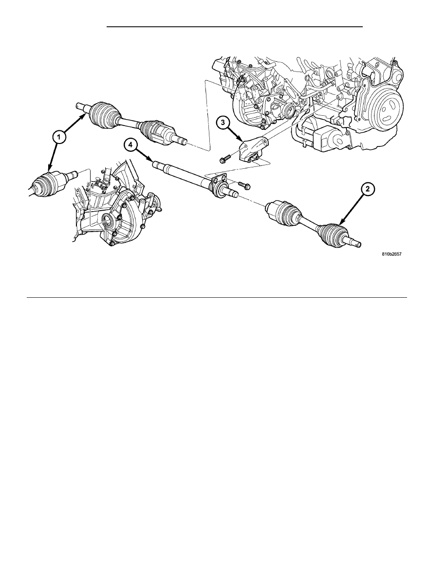
Fig. 17 Halfshaft and Intermediate Shaft—2.4L Turbo Models

1 - HALFSHAFT - LEFT
2 - HALFSHAFT - RIGHT

3 - SUPPORT BRACKET - INTERMEDIATE SHAFT
4 - INTERMEDIATE SHAFT/BEARING ASSEMBLY

3 - 8

HALF SHAFT

PL/SRT-4

HALF SHAFT (Continued)

joint from transaxle by hand. If snap ring is
fully engaged with side gear, tripod joint will
not be removable by hand.

(4) Clean all debris and moisture out of steering

knuckle (Fig. 18).

(5) Ensure that front of outer C/V joint, which fits

into steering knuckle (Fig. 19), is free of debris and
moisture before assembling into steering knuckle.

(6) Slide halfshaft back into front hub. Install

steering knuckle onto the ball joint stud (Fig. 20).

NOTE: At this point, the outer joint will not seat
completely into the front hub. The outer joint will be
pulled into hub and seated when the hub nut is
installed and torqued.

(7) Install a NEW steering knuckle to ball joint

stud bolt and nut (Fig. 20). Tighten the nut and bolt
to 95 N·m (70 ft. lbs.).

(8) Clean all foreign matter from threads of half-

shaft outer stub axle. Install hub nut onto the
threads of the stub axle and tighten nut to 244 N·m
(180 ft. lbs.) (Fig. 21).

(9) Install front wheel and tire assembly. Install

front wheel lug nuts (Fig. 22) and tighten to 128 N·m
(95 ft. lbs.).

Fig. 18 Steering Knuckle to C/V Joint

1 - STEERING KNUCKLE
2 - WHEEL BEARING
3 - FRONT HUB
4 - THIS AREA OF THE STEERING KNUCKLE IS TO BE FREE OF
ALL DEBRIS AND MOISTURE BEFORE INSTALLING DRIVE
SHAFT IN STEERING KNUCKLE

Fig. 19 Outer C/V Joint Inspection

1 - OUTER C/V JOINT
2 - THIS AREA OF OUTER C/V JOINT MUST BE FREE OF ALL
DEBRIS AND MOISTURE, BEFORE INSTALLATION INTO
STEERING KNUCKLE.

Fig. 20 Driveshaft Installation Into Hub And Steering

Knuckle

1 - NUT
2 - BOLT
3 - BALL JOINT

Fig. 21 Halfshaft Retaining Hardware

1 - HUB NUT
2 - NUT LOCK
3 - COTTER PIN
4 - SPRING WASHER

PL/SRT-4

HALF SHAFT

3 - 9

HALF SHAFT (Continued)

(10) Check for correct fluid level in transaxle

assembly.

(11) Lower vehicle.
(12) Connect battery negative cable.

INSTALLATION—2.4L TURBO MODELS

CAUTION: Boot sealing is vital to retain special
lubricants and to prevent foreign contaminants
from entering the C/V joint. Mishandling, such as
allowing the assemblies to dangle unsupported, or
pulling or pushing the ends can cut boots or dam-
age C/V joints. During removal and installation pro-
cedures, always support both ends of the halfshaft
to prevent damage.

(1) If removed, install intermediate shaft/bearing

assembly (Fig. 17). Install and torque bearing-to-
bracket bolts to 54 N·m (40 ft. lbs.).

(2) Install halfshaft(s). Left halfshaft: Thoroughly

clean spline and oil seal sealing surface on left tripod
joint. Lightly lubricate oil seal sealing surface on tri-
pod joint with fresh clean transmission lubricant.
While holding halfshaft assembly by tripod joint and
interconnecting shaft, install tripod joint into trans-
axle as far as possible by hand. Carefully align tripod
joint with transaxle side gears. Then grasp halfshaft
interconnecting shaft and push tripod joint into
transaxle side gear until fully seated. Test that snap
ring is fully engaged with side gear by attempting to
remove tripod joint from transaxle by hand. If snap
ring is fully engaged with side gear, tripod joint will
not be removable by hand. Right halfshaft: Thor-
oughly clean right halfshaft tripod joint spline, as
well as intermediate shaft spline. While holding half-
shaft assembly by tripod joint and interconnecting
shaft, install tripod joint onto intermediate shaft as
far as possible by hand.

(3) Clean all debris and moisture out of steering

knuckle (Fig. 23).

(4) Ensure that front of outer C/V joint, which fits

into steering knuckle (Fig. 24), is free of debris and
moisture before assembling into steering knuckle.

(5) Slide halfshaft back into front hub. Install

steering knuckle onto the ball joint stud (Fig. 25).

NOTE: At this point, the outer joint will not seat
completely into the front hub. The outer joint will be
pulled into hub and seated when the hub nut is
installed and torqued.

Fig. 22 Wheel and Tire Installation

1 - WHEEL/TIRE ASSY.
2 - LUG NUT (5)
3 - HUB

Fig. 23 Steering Knuckle to C/V Joint Sealing Area

1 - STEERING KNUCKLE
2 - WHEEL BEARING
3 - FRONT HUB
4 - THIS AREA OF THE STEERING KNUCKLE IS TO BE FREE OF
ALL DEBRIS AND MOISTURE BEFORE INSTALLING HALFSHAFT
IN STEERING KNUCKLE

Fig. 24 Outer C/V Joint Inspection

1 - OUTER C/V JOINT
2 - THIS AREA OF OUTER C/V JOINT MUST BE FREE OF ALL
DEBRIS AND MOISTURE, BEFORE INSTALLATION INTO
STEERING KNUCKLE.

3 - 10

HALF SHAFT

PL/SRT-4

HALF SHAFT (Continued)

(6) Install a NEW steering knuckle to ball joint

stud bolt and nut (Fig. 25). Tighten the nut and bolt
to 95 N·m (70 ft. lbs.).

(7) Clean all foreign matter from threads of half-

shaft outer stub axle. Install washer and hub nut
onto the threads of the stub axle and tighten nut to
244 N·m (180 ft. lbs.) (Fig. 26).

(8) Install spring washer, nut lock, and cotter pin

(Fig. 26).

(9) Install front wheel and tire assembly. Install

front wheel lug nuts (Fig. 27) and tighten to 128 N·m
(100 ft. lbs.).

(10) Check for correct fluid level in transaxle

assembly.

(11) Lower vehicle.
(12) Connect battery negative cable.

SPECIFICATIONS - TORQUE

TORQUE SPECIFICATIONS

DESCRIPTION

N·m

Ft. Lbs.

In. Lbs.

Bolt, Intermediate Shaft

Bearing-to-Bracket (2.4L

Turbo)

28

250

Bolt, Intermediate Shaft

Bracket-to-Block (2.4L

Turbo)

54

40

Nut, Driveshaft-to-Hub/

Bearing

244

180

Nut, Knuckle-to-Ball Joint

Bolt

95

70

Nut, Wheel to Hub

128

95

Fig. 25 Halfshaft Installation Into Hub And Knuckle

1 - NUT
2 - BOLT
3 - BALL JOINT

Fig. 26 Halfshaft Retaining Hardware

1 - HUB NUT
2 - NUT LOCK
3 - COTTER PIN
4 - SPRING WASHER

Fig. 27 Wheel and Tire Installation

1 - WHEEL/TIRE ASSY.
2 - LUG NUT (5)
3 - HUB

PL/SRT-4

HALF SHAFT

3 - 11

HALF SHAFT (Continued)


Content   ..  24  25  26  27   ..