Dodge Neon / Neon SRT-4. Manual - part 25


  Index      Dodge     Dodge Neon / Neon SRT-4 - service repair manual 2005 year


Search            


Content   ..  23  24  25  26   ..


Dodge Neon / Neon SRT-4. Manual - part 25


Replace only the affected side. Replacing both half-
shafts is not necessary.

(2) A sticking tripod joint spider assembly (inner

tripod joint only). Isolate the condition to one side of
the vehicle. Replace only the affected side. Replacing
both halfshafts is not necessary.

(3) Improper wheel balance.

VIBRATION AT HIGHWAY SPEEDS

(1) Foreign material (mud, etc.) packed on the

backside of the wheel(s).

(2) Out of balance front tires or wheels.
(3) Improper tire and/or wheel runout.

REMOVAL

REMOVAL—EXCEPT 2.4L TURBO MODELS

CAUTION: Boot sealing is vital to retain special
lubricants and to prevent foreign contaminants
from entering the C/V joint. Mishandling, such as
allowing the assemblies to dangle unsupported, or
pulling or pushing the ends can cut boots or dam-
age C/V joints. During removal and installation pro-
cedures, always support both ends of the halfshaft
to prevent damage.

CAUTION: The halfshaft, when installed, acts as a
bolt and secures the front hub/bearing assembly. If
vehicle is to be supported or moved on its wheels
with a halfshaft removed, install a PROPER–SIZED
BOLT AND NUT through front hub. Tighten bolt and
nut to 244 N·m (180 ft. lbs.). This will ensure that
the hub bearing cannot loosen.

(1) Disconnect battery negative cable.
(2) Place transaxle in gated park.
(3) Raise vehicle on hoist.
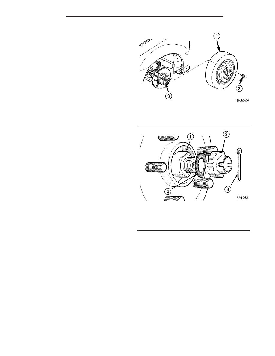
(4) Remove wheel and tire assembly (Fig. 4).
(5) Remove the halfshaft to hub cotter pin, nut

lock, wave washer and hub nut (Fig. 5).

(6) If equipped with ABS, disconnect the front

wheel speed sensor and secure harness out of the
way.

(7) Remove nut and bolt (Fig. 6) retaining ball

joint stud into steering knuckle.

CAUTION: Use caution when separating ball joint
stud from steering knuckle, so ball joint seal does
not get damaged.

(8) Separate ball joint stud from steering knuckle

by prying down on lower control arm (Fig. 7).

CAUTION: Care must be taken not to separate the
inner C/V joint during this operation. Do not allow

halfshaft to hang by inner C/V joint, halfshaft must
be supported.

(9) Remove halfshaft from steering knuckle by

pulling outward on knuckle while pressing in on half-
shaft. Support outer end of halfshaft assembly. If dif-
ficulty in separating halfshaft from steering knuckle
is encountered, use Puller 1026 as shown in (Fig. 8)
to separate shaft. Do not strike shaft with ham-
mer.

(10) Support outer end of the halfshaft assembly.

CAUTION: Do not pull on interconnecting shaft
when removing halfshaft assembly. Inner joint may
become separated.

(11) Remove the inner tripod joints from the side

gears of the transaxle using a punch to dislodge the
inner tripod joint retaining ring from the transaxle
side gear. If removing the right side inner tripod

Fig. 4 Wheel and Tire Removal

1 - WHEEL/TIRE ASSY.
2 - LUG NUT (5)
3 - HUB

Fig. 5 Halfshaft Retaining Hardware

1 - HUB NUT
2 - NUT LOCK
3 - COTTER PIN
4 - SPRING WASHER

3 - 4

HALF SHAFT

PL/SRT-4

HALF SHAFT (Continued)

joint, position punch against the inner tripod joint
(Fig. 9). Strike the punch sharply with a hammer to
dislodge the right inner joint from the side gear. If
removing the left side inner tripod joint, position the
punch in the groove of the inner tripod joint (Fig. 10).
Strike the punch sharply with a hammer to dislodge
the left inner tripod joint from the side gear.

NOTE: Removal of the inner tripod joints is made
easier if you apply outward pressure on the joint as
you strike the punch with a hammer.

(12) Hold inner tripod joint and interconnecting

shaft of halfshaft assembly (Fig. 11). Remove inner

tripod joint from transaxle by pulling it straight out
of transaxle side gear and transaxle oil seal. When
removing tripod joint, do not let spline or snap
ring drag across sealing lip of the transaxle to
tripod joint oil seal. When tripod joint is
removed from transaxle, some fluid will leak
out.

Fig. 6 Steering Knuckle at Lower Control Arm Ball

Joint

1 - NUT
2 - BOLT
3 - BALL JOINT

Fig. 7 Separating Lower Control Arm from Steering

Knuckle

1 - STEERING KNUCKLE
2 - PRY BAR
3 - LOWER CONTROL ARM
4 - BALL JOINT STUD

Fig. 8 Separating Halfshaft from Hub/Bearing

1 - PULLER 1026
2 - HALFSHAFT

Fig. 9 Disengaging Right Inner Tripod Joint from

Transaxle

1 - TRANSAXLE
2 - RIGHT INNER TRIPOD JOINT
3 - PUNCH

PL/SRT-4

HALF SHAFT

3 - 5

HALF SHAFT (Continued)

CAUTION: The halfshaft, when installed, acts as a
bolt and secures the front hub/bearing assembly. If
vehicle is to be supported or moved on its wheels
with a halfshaft removed, install a PROPER–SIZED
BOLT AND NUT through front hub. Tighten bolt and
nut to 244 N·m (180 ft. lbs.). This will ensure that
the hub bearing cannot loosen.

REMOVAL—2.4L TURBO MODELS

CAUTION: Boot sealing is vital to retain special
lubricants and to prevent foreign contaminants
from entering the C/V joint. Mishandling, such as
allowing the assemblies to dangle unsupported, or
pulling or pushing the ends can cut boots or dam-
age C/V joints. During removal and installation pro-
cedures, always support both ends of the halfshaft
to prevent damage.

CAUTION: The halfshaft, when installed, acts as a
bolt and secures the front hub/bearing assembly. If
vehicle is to be supported or moved on its wheels
with a halfshaft removed, install a PROPER–SIZED
BOLT AND NUT through front hub. Tighten bolt and
nut to 244 N·m (180 ft. lbs.). This will ensure that
the hub bearing cannot loosen.

(1) Disconnect battery negative cable.
(2) Place transaxle in gated park.
(3) Raise vehicle on hoist.
(4) Remove wheel and tire assembly (Fig. 12).

(5) Remove the cotter pin, nut lock, and spring

washer, and hub nut from the end of the outer C/V
joint stub axle (Fig. 13).

(6) If equipped with ABS, disconnect the front

wheel speed sensor and secure harness out of the
way.

(7) Remove nut and bolt (Fig. 14) retaining ball

joint stud into steering knuckle.

NOTE: Use caution when separating ball joint stud
from steering knuckle, so ball joint seal does not
get damaged.

Fig. 10 Disengaging Left Inner Tripod Joint from

Transaxle

1 - FRONT SUSPENSION CROSSMEMBER
2 - PUNCH
3 - TRANSAXLE
4 - DRIVESHAFT INNER TRIPOD JOINT
5 - NOTCH

Fig. 11 Tripod Joint Removal from Transaxle

1 - INNER TRIPOD JOINT
2 - TRANSAXLE
3 - SPLINE
4 - OIL SEAL
5 - SNAP RING
6 - INTERCONNECTING SHAFT

Fig. 12 Wheel and Tire Removal

1 - WHEEL/TIRE ASSY.
2 - LUG NUT (5)
3 - HUB

3 - 6

HALF SHAFT

PL/SRT-4

HALF SHAFT (Continued)

(8) Separate ball joint stud from steering knuckle

by prying down on lower control arm (Fig. 15).

NOTE: Care must be taken not to separate the inner
C/V joint during this operation. Do not allow half-
shaft to hang by inner C/V joint, halfshaft must be
supported.

(9) Remove halfshaft from steering knuckle by

pulling outward on knuckle while pressing in on half-
shaft. Support outer end of halfshaft assembly. If dif-
ficulty

in

separating

halfshaft

from

hub

is

encountered, do not strike shaft with hammer,
instead use puller 1026 to separate (Fig. 16).

(10) Support outer end of the halfshaft assembly.

NOTE: When left halfshaft is removed from trans-
axle, some fluid may leak out.

NOTE: Removal of the inner tripod joints is made
easier if you apply outward pressure on the joint as
you strike the punch with a hammer. DO NOT PULL
ON INTERCONNECTING SHAFT TO REMOVE, AS
THE INNER JOINT WILL BECOME SEPARATED.

Fig. 13 Halfshaft Retaining Hardware

1 - HUB NUT
2 - NUT LOCK
3 - COTTER PIN
4 - SPRING WASHER

Fig. 14 Steering Knuckle at Lower Control Arm Ball

Joint

1 - NUT
2 - BOLT
3 - BALL JOINT

Fig. 15 Separating Lower Control Arm from Steering

Knuckle

1 - STEERING KNUCKLE
2 - PRY BAR
3 - LOWER CONTROL ARM
4 - BALL JOINT STUD

Fig. 16 Separating Halfshaft from Hub/Bearing

1 - PULLER 1026
2 - HALFSHAFT

PL/SRT-4

HALF SHAFT

3 - 7

HALF SHAFT (Continued)


Content   ..  23  24  25  26   ..