Dodge Caliber. Manual - part 870


  Index      Dodge     Dodge Caliber - service repair manual 2007 year


Search            


Content   ..  868  869  870  871   ..


Dodge Caliber. Manual - part 870


6.

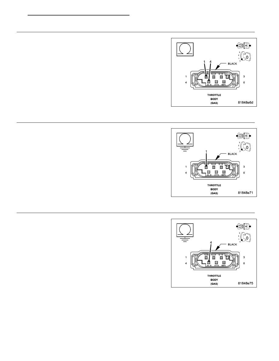
(K124) ETC MOTOR (+) CIRCUIT SHORTED TO THE (K126) ETC MOTOR (-) CIRCUIT

Turn the ignition off.

Measure the resistance between the (K124) ETC Motor (+) circuit and
the (K126) ETC Motor (-) circuit.

Is the resistance below 100 ohms?

Yes

>> Repair the short to between the (K124) ETC Motor (+) cir-

cuit and the (K126) ETC Motor (-) circuit.

Perform the PCM Verification Test Ver. 1 (Refer to 9 -
ENGINE - DIAGNOSIS AND TESTING).

No

>> Go to 7

7.

(K124) ETC MOTOR (+) CIRCUIT SHORTED TO GROUND

Measure the resistance between ground and the (K124) ETC Motor (+)
circuit.

Is the resistance below 100 ohms?

Yes

>> Repair the short to ground in the (K124) ETC Motor (+) cir-

cuit.

Perform the PCM Verification Test Ver. 1 (Refer to 9 -
ENGINE - DIAGNOSIS AND TESTING).

No

>> Go to 8

8.

(K126) ETC MOTOR (-) CIRCUIT SHORTED TO GROUND

Measure the resistance between ground and the (K126) ETC Motor (-)
circuit.

Is the resistance below 100 ohms?

Yes

>> Repair the short to ground in the (K126) ETC Motor (-) cir-

cuit.

Perform the PCM Verification Test Ver. 1 (Refer to 9 -
ENGINE - DIAGNOSIS AND TESTING).

No

>> Go to 9

PM

ENGINE ELECTRICAL DIAGNOSTICS - GPEC

9 - 767

9.

(K126) ETC MOTOR (-) CIRCUIT OPEN OR HIGH RESISTANCE

Measure the resistance of the (K126) ETC Motor (-) circuit.

Is the resistance below 5.0 ohms?

Yes

>> Go to 10

No

>> Repair the (K126) ETC Motor (-) circuit for an open circuit

or high resistance.

Perform the PCM Verification Test Ver. 1 (Refer to 9 -
ENGINE - DIAGNOSIS AND TESTING).

10.

(K124) ETC MOTOR (+) CIRCUIT OPEN OR HIGH RESISTANCE

Measure the resistance of the (K124) ETC Motor (+) circuit.

Is the resistance below 5.0 ohms?

Yes

>> Go to 11

No

>> Repair the (K124) ETC Motor (+) circuit for an open circuit

or high resistance.

Perform the PCM Verification Test Ver. 1 (Refer to 9 -
ENGINE - DIAGNOSIS AND TESTING).

9 - 768

ENGINE ELECTRICAL DIAGNOSTICS - GPEC

PM

11.

POWERTRAIN CONTROL MODULE (PCM)

Using the wiring diagram/schematic as a guide, inspect the wiring and connectors between the Throttle Body and
the Powertrain Control Module (PCM).

Look for any chafed, pierced, pinched, or partially broken wires.

Look for broken, bent, pushed out or corroded terminals.

Refer to any Technical Service Bulletins that may apply.

Were any problems found?

Yes

>> Repair as necessary.

Perform the PCM Verification Test Ver. 1 (Refer to 9 - ENGINE - DIAGNOSIS AND TESTING).

No

>> Replace and program the Powertrain Control Module per Service Information.

Perform the PCM Verification Test Ver. 1 (Refer to 9 - ENGINE - DIAGNOSIS AND TESTING).

PM

ENGINE ELECTRICAL DIAGNOSTICS - GPEC

9 - 769

P2112-ELECTRONIC THROTTLE CONTROL - UNABLE TO OPEN

For a complete wiring diagram Refer to Section 8W.

9 - 770

ENGINE ELECTRICAL DIAGNOSTICS - GPEC

PM


Content   ..  868  869  870  871   ..