Dodge Caliber. Manual - part 837


  Index      Dodge     Dodge Caliber - service repair manual 2007 year


Search            


Content   ..  835  836  837  838   ..


Dodge Caliber. Manual - part 837


5.

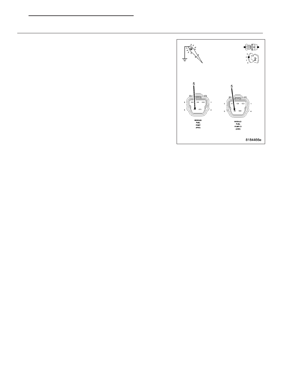
FUEL PUMP CONTROL OUTPUT FROM TIPM

Reconnect the TIPM C7 harness connector.

Ignition on, engine not running.

With a scan tool in the TIPM Actuators, actuate the Fuel Pump.

Using the 12-volt test light connected to ground, probe the (N1) Fuel
Pump Control Output circuit in the Fuel Pump harness connector.

Does the test light illuminate brightly?

Yes

>> Replace the Fuel Pump.

Perform the POWERTRAIN VERIFICATION TEST. (Refer to
9 - ENGINE - STANDARD PROCEDURE)

No

>> Replace the TIPM in accordance with the Service Informa-

tion.

Perform the POWERTRAIN VERIFICATION TEST. (Refer to
9 - ENGINE - STANDARD PROCEDURE)

PM

ENGINE ELECTRICAL DIAGNOSTICS - GPEC

9 - 635

P1501-VEHICLE SPEED SENSOR 1/2 CORRELATION — DRIVE WHEELS

For a complete wiring diagram Refer to Section 8W

9 - 636

ENGINE ELECTRICAL DIAGNOSTICS - GPEC

PM

When Monitored:
With the ignition on and battery voltage greater than 10.4 volts.

Set Condition:
The PCM detects an implausible voltage on the Vehicle Speed Sensor circuit.

Possible Causes

INTERMITTENT DTC

(F856) 5 VOLT SUPPLY CIRCUIT SHORTED TO VOLTAGE

(K75) VEHICLE SPEED SIGNAL CIRCUIT SHORTED TO VOLTAGE

(F856) 5 VOLT SUPPLY CIRCUIT SHORTED TO GROUND

(K75) VEHICLE SPEED SIGNAL CIRCUIT SHORTED TO GROUND

(F856) 5 VOLT SUPPLY CIRCUIT SHORTED TO THE (K75) VEHICLE SPEED SIGNAL CIRCUIT

(F856) 5 VOLT SUPPLY CIRCUIT SHORTED TO THE (K914) SENSOR GROUND CIRCUIT

(K75) VEHICLE SPEED SIGNAL CIRCUIT SHORTED TO THE (K914) SENSOR GROUND CIRCUIT

(F856) 5 VOLT SUPPLY CIRCUIT OPEN OR HIGH RESISTANCE

(K75) VEHICLE SPEED SIGNAL CIRCUIT OPEN OR HIGH RESISTANCE

(K914) SENSOR GROUND CIRCUIT OPEN OR HIGH RESISTANCE

VEHICLE SPEED SENSOR

POWERTRAIN CONTROL MODULE (PCM)

Always perform the Pre-Diagnostic Troubleshooting procedure before proceeding. (Refer to 9 - ENGINE -
DIAGNOSIS AND TESTING)

Diagnostic Test

1.

DTC IS ACTIVE

Start the engine.

Allow the engine to reach normal operating temperature.

NOTE: Diagnose and repair any system voltage or sensor reference voltage DTCs before continuing with
this test.

NOTE: Check for any Bus Communication DTCs. If no Bus or Communication DTCs are set, check for active
Vehicle Speed Sensor DTCs in the Totally Integrated Power Module. Any bus, communication, or VSS DTCs
in the TIPM must be properly diagnosed before continuing.

NOTE: This code may set after a hard acceleration on loose gravel, during other off road driving conditions,
or by any condition that causes a wheel speed difference between the front and rear wheels.

NOTE: It may be necessary to test drive the vehicle within the DTC monitoring conditions in order for this
DTC to set.
With the scan tool, select View DTCs.

Is the status Active for this DTC?

Yes

>> Go to 2

No

>> Refer to the *CHECKING FOR AN INTERMITTENT DTC Diagnostic Procedure. (Refer to 9 - ENGINE -

DIAGNOSIS AND TESTING)

PM

ENGINE ELECTRICAL DIAGNOSTICS - GPEC

9 - 637

2.

(F856) 5 VOLT SUPPLY CIRCUIT VOLTAGE

Turn the ignition off.

Disconnect the Vehicle Speed Sensor connector.

Turn the ignition on.

Measure the voltage of the (F856) 5 Volt Supply circuit in the Vehicle
Speed Sensor harness connector.

Is the voltage between 4.5 and 5.5 volts?

Yes

>> Go to 3

No

>> Go to 7

3.

(K75) VEHICLE SPEED SIGNAL CIRCUIT VOLTAGE

Measure the voltage of the (K75) Vehicle Speed Signal circuit in the
Vehicle Speed Sensor harness connector.

Is the voltage between 4.5 and 5.5 volts?

Yes

>> Go to 4

No

>> Go to 11

4.

(K914) SENSOR GROUND CIRCUIT TEST

Turn the ignition off.

Using a 12 volt test light connected to 12 volts, check the (K914) Sensor Ground in the Vehicle Speed Sensor
harness connector.

NOTE: The test light should be illuminated and bright. Compare the brightness to that of a direct connec-
tion to the battery.

Is the test light illuminated and bright?

Yes

>> Go to 5

No

>> Go to 15

9 - 638

ENGINE ELECTRICAL DIAGNOSTICS - GPEC

PM


Content   ..  835  836  837  838   ..