Dodge Caliber. Manual - part 807
3.
CLOCKSPRING
Turn the ignition off.
Disconnect the Steering Control Module (SCM) C5 harness connector.
Turn the ignition on.
With a scan tool, read the (V72) S/C Signal 2 voltage.
NOTE: The voltage should be above 4.8 volts with the Steering Control Module (SCM) C5 connector dis-
connected.
Connect a jumper wire between the (V72) S/C Signal 2 circuit and the (V937) S/C Switch Ground circuit at the
Steering Control Module (SCM) C5 connector, not at the harness connector.
With a scan tool, read the (V72) S/C Signal 2 voltage.
NOTE: The (V72) S/C Signal 2 voltage should be below .2 volts with the jumper wire in place.
Are the Speed Control voltages displayed as described?
Yes
>> Replace the Clockspring in accordance with the Service Information.
Perform the PCM Verification Test Ver. 1 (Refer to 9 - ENGINE - DIAGNOSIS AND TESTING).
No
>> Go to 4
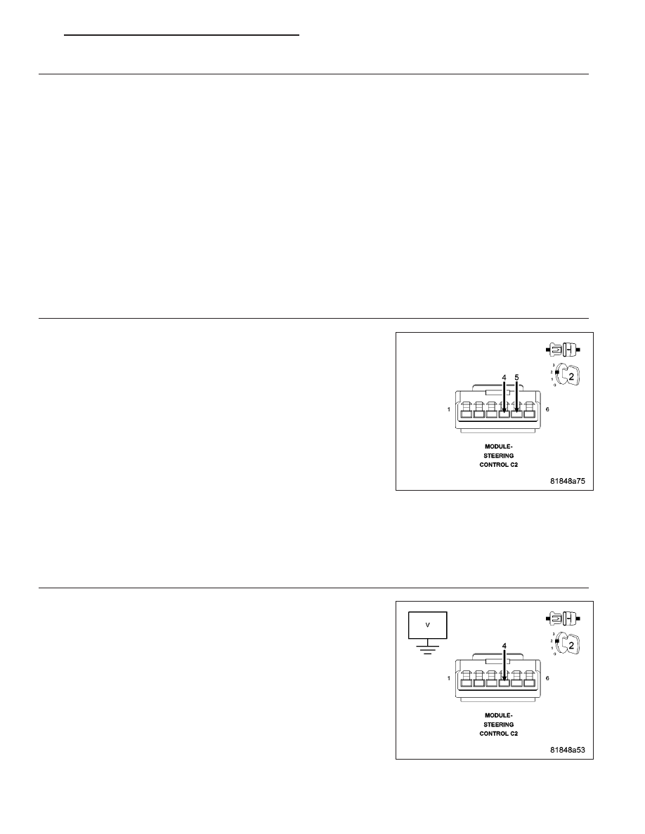
4.
STEERING CONTROL MODULE (SCM)
Turn the ignition off.
Disconnect the Steering Control Module (SCM) C2 connector.
Turn the ignition on.
With a scan tool, read the (V72) S/C Signal 2 voltage.
NOTE: The voltage should be above 4.8 volts with the connector
disconnected.
Connect a jumper wire between the (V72) S/C Signal 2 circuit and the
(V937) S/C Switch Ground circuit in the Steering Control Module (SCM)
C2 harness connector.
With a scan tool, read the (V72) S/C Signal 2 voltage.
NOTE: The (V72) S/C Signal 2 voltage should be below .2 volts
with the jumper wire in place.
Are the Speed Control voltages displayed as described?
Yes
>> Replace the Steering Control Module (SCM) in accordance with the Service Information.
Perform the PCM Verification Test Ver. 1 (Refer to 9 - ENGINE - DIAGNOSIS AND TESTING).
No
>> Go to 5
5.
(V72) S/C SIGNAL 2 CIRCUIT SHORTED TO VOLTAGE
Turn the ignition off.
Disconnect the Powertrain Control Module (PCM) connector.
Turn the ignition on.
Measure the voltage of the (V72) S/C Signal 2 circuit in the Steering
Control Module (SCM) harness connector.
Is there any voltage present?
Yes
>> Repair the (V72) S/C Signal 2 circuit for a short to voltage.
Perform the PCM Verification Test Ver. 1 (Refer to 9 -
ENGINE - DIAGNOSIS AND TESTING).
No
>> Go to 6
PM
ENGINE ELECTRICAL DIAGNOSTICS - GPEC
9 - 515