Dodge Caliber. Manual - part 805
•
When Monitored:
With the ignition on and battery voltage greater than 10.4 volts.
•
Set Condition:
The ECM detects that the (V71) S/C Signal 1 voltage does not match the (V72) S/C Signal 2 voltage.
Possible Causes
INTERMITTENT DTC
(V71) S/C SIGNAL 1 CIRCUIT SHORTED TO VOLTAGE
(V72) S/C SIGNAL 2 CIRCUIT SHORTED TO VOLTAGE
(V71) S/C SIGNAL 1 CIRCUIT SHORTED TO GROUND
(V72) S/C SIGNAL 2 CIRCUIT SHORTED TO GROUND
(V71) S/C SIGNAL 1 CIRCUIT SHORTED TO THE (V937) S/C SWITCH GROUND CIRCUIT
(V72) S/C SIGNAL 2 CIRCUIT SHORTED TO THE (V937) S/C SWITCH GROUND CIRCUIT
(V71) S/C SIGNAL 1 CIRCUIT OPEN OR HIGH RESISTANCE
(V72) S/C SIGNAL 2 CIRCUIT OPEN OR HIGH RESISTANCE
(V937) S/C SWITCH GROUND CIRCUIT OPEN OR HIGH RESISTANCE
CLOCKSPRING
SPEED CONTROL SWITCH
STEERING CONTROL MODULE (SCM)
POWERTRAIN CONTROL MODULE (PCM)
Always perform the Pre-Diagnostic Troubleshooting procedure before proceeding. (Refer to 9 - ENGINE -
DIAGNOSIS AND TESTING)
Diagnostic Test
1.
DTC IS ACTIVE
Turn the ignition on.
With a scan tool, select View DTCs.
Is the status Active for this DTC?
Yes
>> Go to 2
No
>> Refer to the *CHECKING FOR AN INTERMITTENT DTC Diagnostic Procedure. (Refer to 9 - ENGINE -
DIAGNOSIS AND TESTING)
2.
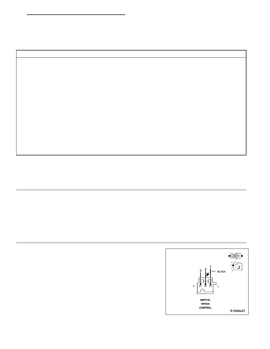
SPEED CONTROL SWITCH
Turn the ignition off.
Remove the Speed Control Switch in accordance with the Service Infor-
mation.
Turn the ignition on.
With a scan tool, read the (V71) S/C Signal 1 and (V72) S/C Signal 2
voltages.
NOTE: The voltages should be above 4.8 volts with the Speed Con-
trol Switch connector disconnected.
Connect a jumper wire between the (V71) S/C Signal 1 circuit and the
(V937) S/C Switch Ground circuit in the Speed Control Switch harness
connector.
With a scan tool, read the (V71) S/C Signal 1 voltage.
PM
ENGINE ELECTRICAL DIAGNOSTICS - GPEC
9 - 507