Dodge Caliber. Manual - part 785


  Index      Dodge     Dodge Caliber - service repair manual 2007 year


Search            


Content   ..  783  784  785  786   ..


Dodge Caliber. Manual - part 785


5.

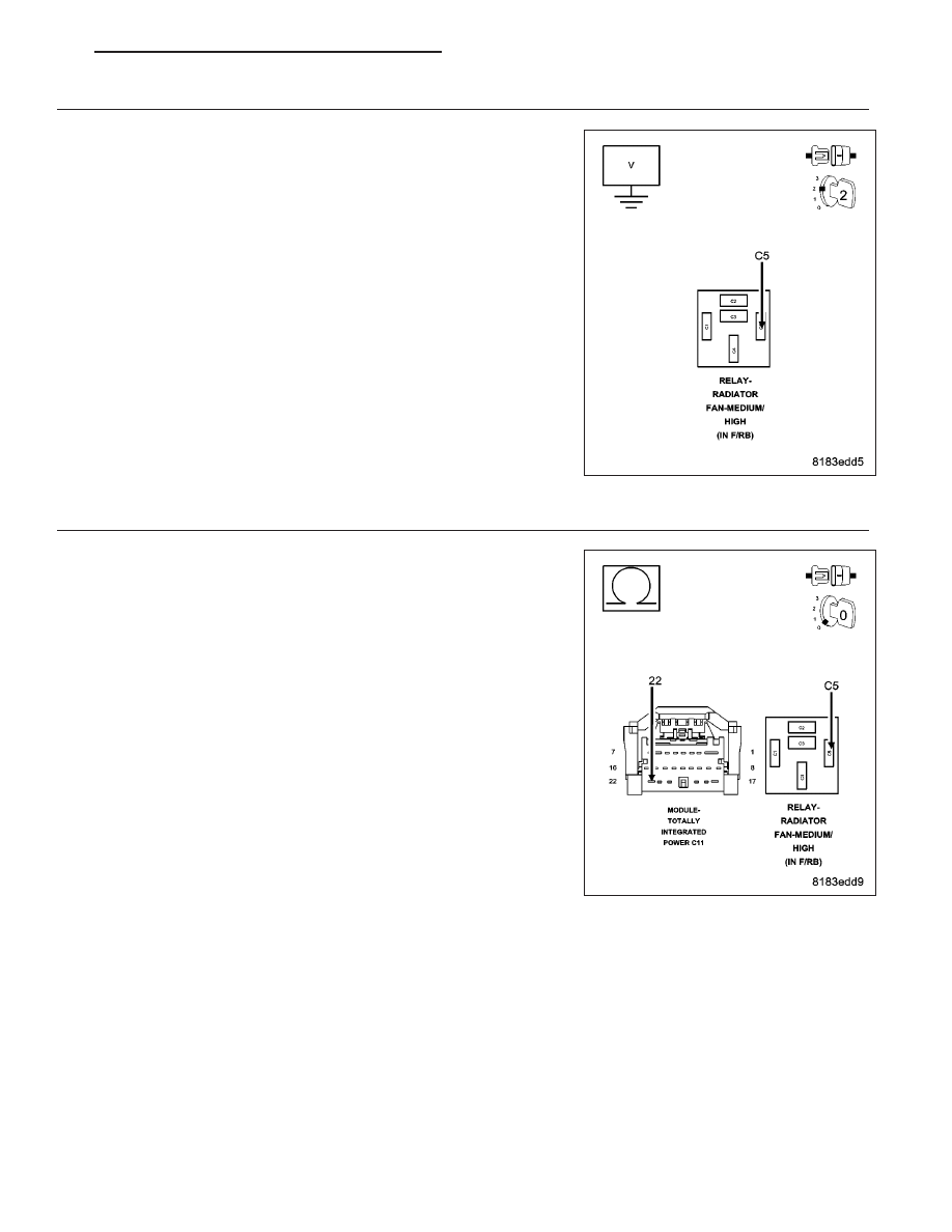
(N112) RAD FAN RELAY CONTROL CIRCUIT SHORTED TO BATTERY VOLTAGE

Disconnect the TIPM C11 harness connector.

Using a voltmeter, measure the voltage of the (N112) Rad Fan Relay
Control circuit in the Med/High Rad Fan Relay harness connector.

Is there voltage present?

Yes

>> Repair the short to voltage in the (N112) Rad Fan Relay

Control circuit.

Perform the POWERTRAIN VERIFICATION TEST. (Refer to
9 - ENGINE - STANDARD PROCEDURE)

No

>> Go To 6

6.

(N112) RAD FAN RELAY CONTROL CIRCUIT OPEN

Measure the resistance of the (N112) Rad Fan Relay Control circuit
from the Med/High Rad Fan Relay harness connector to the TIPM C11
harness connector.

Is the resistance below 5.0 ohms?

Yes

>> Go To 7

No

>> Repair the open in the (N112) Rad Fan Relay Control cir-

cuit.

Perform the POWERTRAIN VERIFICATION TEST. (Refer to
9 - ENGINE - STANDARD PROCEDURE)

PM

ENGINE ELECTRICAL DIAGNOSTICS - GPEC

9 - 427

7.

(N112) RAD FAN RELAY CONTROL CIRCUIT SHORTED TO GROUND

Measure the resistance between ground and the (N112) Rad Fan Relay
Control circuit in the TIPM C11 harness connector.

Is the resistance below 100 ohms?

Yes

>> Repair the short to ground in the (N112) Rad Fan Relay

Control circuit.

Perform the POWERTRAIN VERIFICATION TEST. (Refer to
9 - ENGINE - STANDARD PROCEDURE)

No

>> Replace the Totally Integrated Power Module in accordance

with the Service Information.

Perform the POWERTRAIN VERIFICATION TEST. (Refer to
9 - ENGINE - STANDARD PROCEDURE)

9 - 428

ENGINE ELECTRICAL DIAGNOSTICS - GPEC

PM

P0501-VEHICLE SPEED SENSOR 1 PERFORMANCE

For a complete wiring diagram Refer to Section 8W.

Theory of Operation

The vehicle speed sensor rationality is a continuous test that monitors the vehicle speed sensor for lack of activity.
The rationality will not run if a limp-in exists for MAP, Throttle Position, and Engine Coolant Temperature. If vehicle
speed sensor is below a minimum threshold for a period of time after the vehicle is operated at a sufficient load, a
failure will be indicated.

When Monitored:
With the engine running, transmission not in park or neutral, brakes not applied, and engine RPM greater than
1500.

Set Condition:
This code will set if no vehicle speed signal is received from the ABS Module for more than 11 seconds for 2
consecutive trips. Two Trip Fault. Three good trips to turn off the MIL.

Possible Causes

ACTIVE BUS OR COMMUNICATION DTCS

TIRE CIRCUMFERENCE

PCM

Always perform the Pre-Diagnostic Troubleshooting procedure before proceeding. (Refer to 9 - ENGINE -
DIAGNOSIS AND TESTING).

Diagnostic Test

1.

ACTIVE DTC

Ignition on, engine not running.

NOTE: Check for any Bus Communication DTCs. If no Bus or Communication DTCs are set, check for active
DTCs in the Anti-Lock Brake Module. Any bus, communication, or VSS DTCs in the Anti-Lock Brake Module
must be properly diagnosed before continuing.
With a scan tool, select View DTCs.

Is the status Active for this DTC?

Yes

>> Go to 2

No

>> Refer to the INTERMITTENT CONDITION Diagnostic Procedure.

Refer to the *CHECKING FOR AN INTERMITTENT DTC Diagnostic Procedure. (Refer to 9 - ENGINE -
DIAGNOSIS AND TESTING)

2.

VISUAL INSPECTION

NOTE: This code can set due to tire circumference differences and from the front or rear wheels being on
a slippery surface while the opposite tires are not.
This code may also set on a hard acceleration on loose gravel or during other off road driving conditions.

Check tire pressure of all the tires.

Check tire wear on all the tires.

Ask the customer what the road and driving conditions were like when the fault set.

Were any problems found?

Yes

>> Repair as necessary. If the code set during a front OR rear wheel spin condition, no repair is necessary.

Perform the PCM Verification Test Ver. 1 (Refer to 9 - ENGINE - DIAGNOSIS AND TESTING).

No

>> Go to 3

PM

ENGINE ELECTRICAL DIAGNOSTICS - GPEC

9 - 429

3.

POWERTRAIN CONTROL MODULE (PCM)

Using the wiring diagram/schematic as a guide, inspect the wiring and connectors related to this circuit.

Look for any chafed, pierced, pinched, or partially broken wires.

Look for broken, bent, pushed out or corroded terminals.

Refer to any Technical Service Bulletins that may apply.

Were any problems found?

Yes

>> Repair as necessary.

Perform the PCM Verification Test Ver. 1 (Refer to 9 - ENGINE - DIAGNOSIS AND TESTING).

No

>> Replace and program the Powertrain Control Module (PCM) in accordance with the Service Information.

Perform the PCM Verification Test Ver. 1 (Refer to 9 - ENGINE - DIAGNOSIS AND TESTING).

9 - 430

ENGINE ELECTRICAL DIAGNOSTICS - GPEC

PM


Content   ..  783  784  785  786   ..