Dodge Caliber. Manual - part 754


  Index      Dodge     Dodge Caliber - service repair manual 2007 year


Search            


Content   ..  752  753  754  755   ..


Dodge Caliber. Manual - part 754


3.

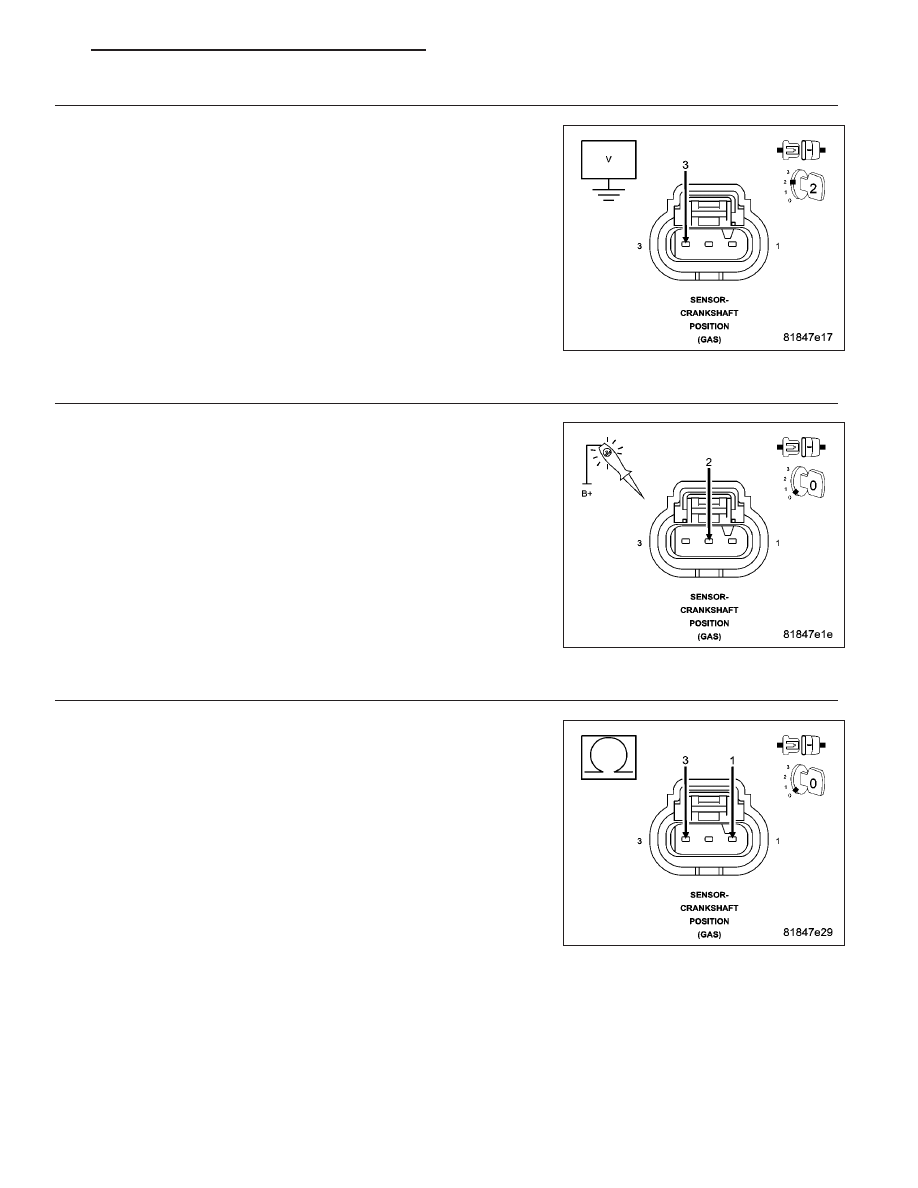
(K24) CKP SIGNAL CIRCUIT VOLTAGE

Measure the voltage of the (K24) CKP Signal circuit in the Crankshaft
Position Sensor harness connector.

Is the voltage between 4.5 and 5.5 volts?

Yes

>> Go to 4

No

>> Go to 11

4.

(K900) SENSOR GROUND CIRCUIT

Turn the ignition off.

Using a 12 volt test light connected to 12 volts, check the (K900) Sen-
sor Ground in the Crankshaft Position Sensor harness connector.

NOTE: The test light should be illuminated and bright. Compare
the brightness to that of a direct connection to the battery.

Is the test light illuminated and bright?

Yes

>> Go to 5

No

>> Go to 15

5.

(F855) 5 VOLT SUPPLY CIRCUIT SHORTED TO THE (K24) CKP SIGNAL CIRCUIT

Measure the resistance between the (F855) 5 Volt Supply circuit and
the (K24) CKP Signal circuit in the Crankshaft Position Sensor harness
connector.

Is the resistance above 100 ohms?

Yes

>> Go to 6

No

>> Repair the (F855) 5 Volt Supply circuit for a short to the

(K24) CKP Signal circuit.

Perform the PCM Verification Test Ver. 1 (Refer to 9 -
ENGINE - DIAGNOSIS AND TESTING).

PM

ENGINE ELECTRICAL DIAGNOSTICS - GPEC

9 - 303

6.

CRANKSHAFT POSITION SENSOR

Using the wiring diagram/schematic as a guide, inspect the wiring and connectors between the Crankshaft Position
Sensor and the Powertrain Control Module (PCM).

Look for any chafed, pierced, pinched, or partially broken wires.

Look for broken, bent, pushed out or corroded terminals.

Inspect the Crankshaft Position Sensor for conditions such as loose mounting screws, damage, or cracks.

If no other problems are found, remove the Crankshaft Position Sensor.

Inspect the Crankshaft Position Sensor and mounting area for any condition that would result in an incorrect signal,
such as damage, foreign material, or excessive movement.

Were any problems found?

Yes

>> Repair as necessary.

Perform the PCM Verification Test Ver. 1 (Refer to 9 - ENGINE - DIAGNOSIS AND TESTING).

No

>> Replace the Crankshaft Position Sensor.

Perform the PCM Verification Test Ver. 1 (Refer to 9 - ENGINE - DIAGNOSIS AND TESTING).

7.

(F855) 5 VOLT SUPPLY CIRCUIT SHORTED TO VOLTAGE

Turn the ignition off.

Disconnect the Powertrain Control Module (PCM) connector.

Turn the ignition on.

Measure the voltage of the (F855) 5 Volt Supply circuit in the Crank-
shaft Position Sensor harness connector.

Is there any voltage present?

Yes

>> Repair the (F855) 5 Volt Supply circuit for a short to volt-

age.

Perform the PCM Verification Test Ver. 1 (Refer to 9 -
ENGINE - DIAGNOSIS AND TESTING).

No

>> Go to 8

8.

(F855) 5 VOLT SUPPLY CIRCUIT SHORTED TO GROUND

Turn the ignition off.

Measure the resistance between ground and the (F855) 5 Volt Supply
circuit in the Crankshaft Position Sensor harness connector.

Is the resistance above 100 ohms?

Yes

>> Go to 9

No

>> Repair the (F855) 5 Volt Supply circuit for a short to ground.

Perform the PCM Verification Test Ver. 1 (Refer to 9 -
ENGINE - DIAGNOSIS AND TESTING).

9 - 304

ENGINE ELECTRICAL DIAGNOSTICS - GPEC

PM

9.

(F855) 5 VOLT SUPPLY CIRCUIT SHORTED TO THE (K900) SENSOR GROUND CIRCUIT

Measure the resistance between the (F855) 5 Volt Supply circuit and
the (K900) Sensor Ground circuit in the Crankshaft Position Sensor har-
ness connector.

Is the resistance above 100 ohms?

Yes

>> Go to 10

No

>> Repair the (F855) 5 Volt Supply circuit for a short to the

(K900) Sensor Ground circuit.

Perform the PCM Verification Test Ver. 1 (Refer to 9 -
ENGINE - DIAGNOSIS AND TESTING).

10.

(F855) 5 VOLT SUPPLY CIRCUIT OPEN OR HIGH RESISTANCE

Measure the resistance of the (F855) 5 Volt Supply circuit between the
Crankshaft Position Sensor harness connector and the Powertrain Con-
trol Module (PCM) harness connector.

Is the resistance below 5.0 ohms?

Yes

>> Go to 16

No

>> Repair the (F855) 5 Volt Supply circuit for an open circuit or

high resistance.

Perform the PCM Verification Test Ver. 1 (Refer to 9 -
ENGINE - DIAGNOSIS AND TESTING).

11.

(K24) CKP SIGNAL CIRCUIT SHORTED TO VOLTAGE

Turn the ignition off.

Disconnect the Powertrain Control Module (PCM) connector.

Turn the ignition on.

Measure the voltage of the (K24) CKP Signal circuit in the Crankshaft
Position Sensor harness connector.

Is there any voltage present?

Yes

>> Repair the (K24) CKP Signal circuit for a short to voltage.

Perform the PCM Verification Test Ver. 1 (Refer to 9 -
ENGINE - DIAGNOSIS AND TESTING).

No

>> Go to 12

PM

ENGINE ELECTRICAL DIAGNOSTICS - GPEC

9 - 305

12.

(K24) CKP SIGNAL CIRCUIT SHORTED TO GROUND

Turn the ignition off.

Measure the resistance between ground and the (K24) CKP Signal cir-
cuit in the Crankshaft Position Sensor harness connector.

Is the resistance above 100 ohms?

Yes

>> Go to 13

No

>> Repair the (K24) CKP Signal circuit for a short to ground.

Perform the PCM Verification Test Ver. 1 (Refer to 9 -
ENGINE - DIAGNOSIS AND TESTING).

13.

(K24) CKP SIGNAL CIRCUIT SHORTED TO (K900) SENSOR GROUND CIRCUIT

Measure the resistance between the (K24) CKP Signal circuit and the
(K900) Sensor Ground circuit in the Crankshaft Position Sensor harness
connector.

Is the resistance above 100 ohms?

Yes

>> Go to 14

No

>> Repair the (K24) CKP Signal circuit for a short to the (K900)

Sensor Ground circuit.

Perform the PCM Verification Test Ver. 1 (Refer to 9 -
ENGINE - DIAGNOSIS AND TESTING).

14.

(K24) CKP SIGNAL CIRCUIT OPEN OR HIGH RESISTANCE

Measure the resistance of the (K24) CKP Signal circuit between the
Crankshaft Position Sensor harness connector and the Powertrain Con-
trol Module (PCM) harness connector.

Is the resistance below 5.0 ohms?

Yes

>> Go to 16

No

>> Repair the (K24) CKP Signal circuit for an open circuit or

high resistance.

Perform the PCM Verification Test Ver. 1 (Refer to 9 -
ENGINE - DIAGNOSIS AND TESTING).

9 - 306

ENGINE ELECTRICAL DIAGNOSTICS - GPEC

PM


Content   ..  752  753  754  755   ..