Dodge Caliber. Manual - part 677


  Index      Dodge     Dodge Caliber - service repair manual 2007 year


Search            


Content   ..  675  676  677  678   ..


Dodge Caliber. Manual - part 677


FUSE BLOCK

DESCRIPTION

An electrical Fuse Block is located in the left front
bumper fascia. It serves to simplify and centralize
numerous electrical components, as well as to distrib-
ute electrical current to many of the accessory sys-
tems in the vehicle.

The Fuse Block is positioned on a mounting bracket
up and under the left instrument panel. It is secured
by two screws. The fuse block is concealed behind a
fuse panel cover. The fuse panel cover is a snap-fit
access cover that conceals the fuse block fuses. A
fuse layout placard is on the back of the end cap to
ensure proper fuse identification.

OPERATION

The fuse block houses blade-type fuses and automatic resetting circuit breakers. Internal connection of all the fuse
block circuits is accomplished by an intricate network of hard wiring and bus bars. Refer to Wiring Diagrams for
complete circuit diagrams.

The fuses and circuit breakers are available for service replacement. The fuse block unit cannot be repaired and is
only serviced as an assembly. If any circuit or the fuse block housing is faulty or damaged, the entire fuse block
must be replaced.

REMOVAL

WARNING: ON VEHICLES EQUIPPED WITH AIR-
BAGS, REFER TO RESTRAINT SYSTEMS BEFORE
ATTEMPTING

ANY

STEERING

COLUMN

OR

INSTRUMENT PANEL COMPONENT DIAGNOSIS
OR SERVICE. FAILURE TO TAKE THE PROPER
PRECAUTIONS COULD RESULT IN ACCIDENTAL
AIRBAG

DEPLOYMENT

AND

POSSIBLE

PER-

SONAL INJURY.

1. Disconnect and isolate the battery negative cable.

2. Remove the front bumper fascia. (Refer to 13 -

FRAME & BUMPERS/BUMPERS/FRONT FASCIA -
INSTALLATION).

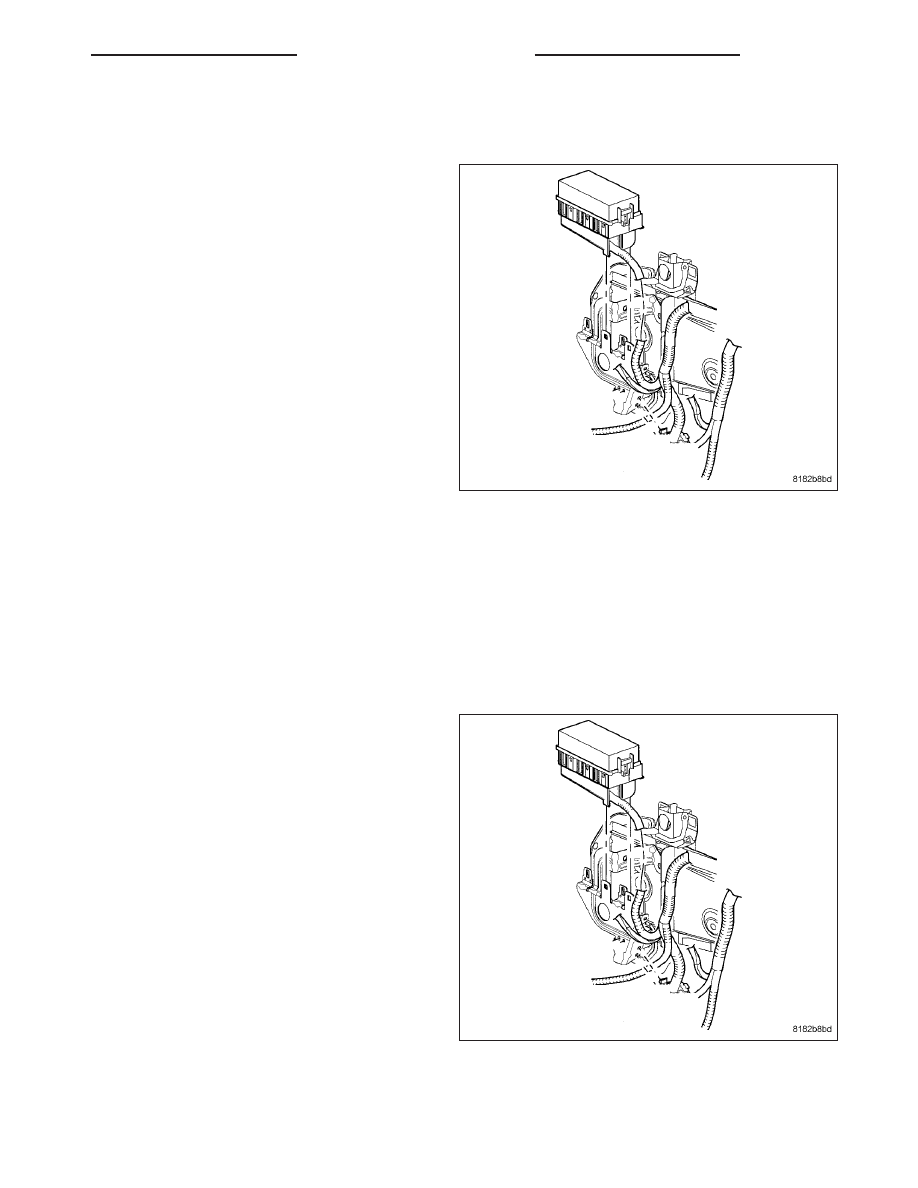
3. Remove mounting fasteners.

4. Remove the wire harness and fuse block.

PM

8W-97 POWER DISTRIBUTION

8W - 97 - 5

INSTALLATION

WARNING: ON VEHICLES EQUIPPED WITH AIR-
BAGS, REFER TO RESTRAINT SYSTEMS BEFORE
ATTEMPTING

ANY

STEERING

COLUMN

OR

INSTRUMENT PANEL COMPONENT DIAGNOSIS
OR SERVICE. FAILURE TO TAKE THE PROPER
PRECAUTIONS COULD RESULT IN ACCIDENTAL
AIRBAG

DEPLOYMENT

AND

POSSIBLE

PER-

SONAL INJURY.

1. Install the new wire harness and fuse block.

2. Install mounting fasteners.

3. Install the front bumper fascia. (Refer to 13 -

FRAME & BUMPERS/BUMPERS/FRONT FASCIA -
REMOVAL).

4. Connect the battery negative cable.

8W - 97 - 6

8W-97 POWER DISTRIBUTION

PM

IOD FUSE

DESCRIPTION

All vehicles are equipped with an Ignition-Off Draw (IOD) fuse that is disconnected within the Totally Integrated
Power Module (TIPM) when the vehicle is shipped from the factory. Dealer personnel are to reconnect the IOD fuse
in the TIPM as part of the preparation procedures performed just prior to new vehicle delivery.

OPERATION

The term ignition-off draw identifies a normal condition where power is being drained from the battery with the igni-
tion switch in the Off position. The IOD fuse feeds the memory and sleep mode functions for some of the electronic
modules in the vehicle as well as various other accessories that require battery current when the ignition switch is
in the Off position, including the clock. The only reason the IOD fuse is disconnected is to reduce the normal IOD
of the vehicle electrical system during new vehicle transportation and pre-delivery storage to reduce battery deple-
tion, while still allowing vehicle operation so that the vehicle can be loaded, unloaded and moved as needed by both
vehicle transportation company and dealer personnel.

The IOD fuse is disconnected from Totally Integrated Power Module (TIPM) fuse cavity 18 when the vehicle is
shipped from the assembly plant. Dealer personnel must reconnect the IOD fuse when the vehicle is being prepared
for delivery in order to restore full electrical system operation. Once the vehicle is prepared for delivery, the IOD
function of this fuse becomes transparent and the fuse that has been assigned the IOD designation becomes only
another Fused B(+) circuit fuse. The IOD fuse serves no useful purpose to the dealer technician in the service or
diagnosis of any vehicle system or condition, other than the same purpose as that of any other standard circuit
protection device.

The IOD fuse can be used by the vehicle owner as a convenient means of reducing battery depletion when a vehi-
cle is to be stored for periods not to exceed about thirty days. However, it must be remembered that disconnecting
the IOD fuse will not eliminate IOD, but only reduce this normal condition. If a vehicle will be stored for more than
about thirty days, the battery negative cable should be disconnected to eliminate normal IOD; and, the battery
should be tested and recharged at regular intervals during the vehicle storage period to prevent the battery from
becoming discharged or damaged.

REMOVAL

NOTE: When removing or installing the IOD fuse, it is important that the ignition switch be in the Off posi-
tion. Failure to place the ignition switch in the Off position can cause the radio display to become scram-
bled when the IOD fuse is installed. Removing and installing the IOD fuse again with the ignition switch in
the Off position will usually correct the scrambled radio display condition.

1. Turn the ignition switch to the Off position.

2. Remove the cover from the Totally Integrated Power Module (TIPM).

3. Remove fuse 7/8 from the TIPM.

INSTALLATION

1. Insert fuse 7/8 into the Totally Integrated Power Module (TIPM).

2. Install the cover to the TIPM.

PM

8W-97 POWER DISTRIBUTION

8W - 97 - 7

POWER DISTRIBUTION CENTER

DESCRIPTION

All of the electrical current distributed throughout this vehicle is directed through the standard equipment Totally
Integrated Power Module (TIPM) (1). The molded plastic TIPM housing is located in the left front corner of the
engine compartment, just behind the air cleaner housing and the battery. The TIPM housing has a molded plastic
cover. The TIPM cover is easily removed for service access and has a convenient fuse and relay layout label affixed
to the inside surface of the cover to ensure proper component identification.

The TIPM housing is secured to the left inner fender well an indexing pin and one screw. All of the TIPM outputs are
through the integral engine compartment wire harness.

OPERATION

All of the current from the generator cable connection goes to the battery through a 10 gauge fusible link that is
secured with a nut to the positive battery terminal at the starter. Internal connection of all the Totally Integrated
Power Module (TIPM) circuits is accomplished by an intricate network of hard wiring and bus bars. Refer to Wiring
Diagrams for complete circuit diagrams.

The fusible link, fuses and relays are available for service replacement. The TIPM unit cannot be repaired and is
only serviced as a unit with the engine compartment wire harness. If the TIPM is inoperative or damaged, the
engine compartment wire harness assembly must be replaced.

REMOVAL

The TIPM (TIPM) is serviced as a unit with the engine compartment wire harness. If any internal circuit of the TIPM
or the TIPM housing is faulty or damaged, the entire TIPM and engine compartment wire harness unit must be
replaced. Refer to Wiring Diagrams for more information on the locations of the affected connectors.

1. Open hood.

2. Disconnect and isolate the battery negative cable.

3. Disconnect each of the engine compartment wire harness connectors.

4. Remove the fasteners that secure each of the engine compartment wire harness ground eyelets to the vehicle

body and chassis components.

5. Disengage each of the retainers that secure the engine compartment wire harness to the vehicle body and chas-

sis components.

6. Disengage and remove the TIPM housing from its mounting bracket.

7. Remove the TIPM and the engine compartment wire harness from the engine compartment as a unit.

INSTALLATION

The Totally Integrated Power Module (TIPM) is serviced as a unit with the engine compartment wire harness. If any
internal circuit of the TIPM or the TIPM housing is faulty or damaged, the entire TIPM and engine compartment wire
harness unit must be replaced.

NOTE: If the power distribution center (TIPM) is being replaced with a new unit, be certain to transfer each
of the fuses and relays from the old power distribution center to the proper cavities of the new power dis-
tribution center. Refer to Wiring Diagrams for the proper power distribution center cavity assignments.

1. Position the TIPM in the engine compartment.

2. Align the TIPM on its mounting bracket and install.

3. Route the engine compartment wire harness from the TIPM through the engine compartment, engaging each of

the harness retainers to the mounting provisions in the vehicle body and chassis components. Refer to Wiring
Diagrams for more information on the harness routing and retainer locations.

4. Install and tighten the fasteners that secure each of the engine compartment wire harness ground eyelets to the

vehicle body and chassis components. Refer to Wiring Diagrams for more information on the ground eyelet loca-
tions.

5. Reconnect each of the engine compartment wire harness connectors. Refer to Wiring Diagrams for more infor-

mation on the locations of the affected connectors.

8W - 97 - 8

8W-97 POWER DISTRIBUTION

PM


Content   ..  675  676  677  678   ..