Dodge Caliber. Manual - part 399


  Index      Dodge     Dodge Caliber - service repair manual 2007 year


Search            


Content   ..  397  398  399  400   ..


Dodge Caliber. Manual - part 399


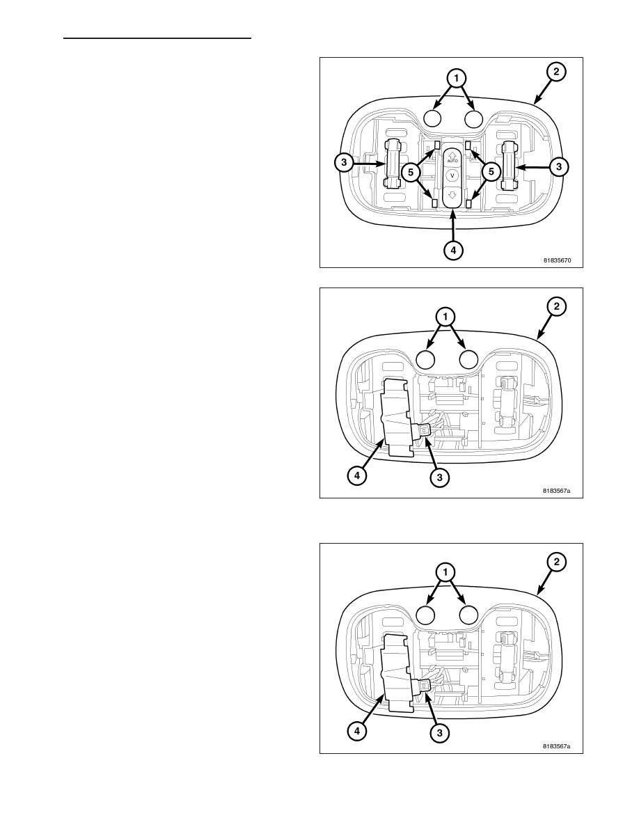
3. Using a suitable flat bladed tool, release the

mounting tabs (5) from the sides of the sunroof
control switch (4) and pull the switch down from the
courtesy/reading lamp assembly (2).

4. Disconnect the electrical connector (3) from the

sunroof control switch (4).

5. Remove the switch from the vehicle.

INSTALLATION

1. Position the sunroof control switch (4) into the vehi-

cle.

2. Connect the sunroof control switch electrical con-

nector (3).

PM

POWER TOP - SUNROOF - SERVICE INFORMATION

8N - 73

3. Insert the sunroof control switch (4) into the cour-

tesy/reading lamp assembly (2). Push up on the
switch until it is securely held in place by the
mounting tabs (5).

4. Insert the mounting tab (4) on the lamp lens (5)

into the right side of the lamp assembly and pivot
the lens up until it snaps securely in place.

5. Connect the negative battery cable.

8N - 74

POWER TOP - SUNROOF - SERVICE INFORMATION

PM

POWER WINDOWS

DESCRIPTION

The power window system allows each of the door windows to be raised and lowered electrically by actuating a
switch on the driver’s door trim panel. The front window switch allows the front occupants to lock out the individual
rear switches from operation. The power window system receives battery feed through a circuit breaker in the fuse
block, only when the ignition switch is in the ON position.

The power window system includes the power window switches on the driver’s door trim panel, passenger door and
rear doors, the circuit breaker in the fuse block, and the power window motors.

OPERATION

The front and rear window lift motors are of the permanent magnet type. A battery positive and negative connection
to either of the two motor terminals will cause the motor to rotate in one direction. Reversing current through these
same two connections will cause the motor to rotate in the opposite direction.

Each individual motor is grounded through their respective switch.

DIAGNOSIS AND TESTING - POWER WINDOWS

WIRING VOLTAGE TEST

The following wiring test determines whether or not voltage is continuous through the body harness to the front
switch.

1. Remove the power window switch and bezel.

2. Disconnect wire connector from back of power window switch.

3. Switch ignition to the ON position.

4. Connect the clip end of a 12 volt test light to Pin 4 of the window switch harness connector. Touch the test light

probe to Pin 3.

If the test light illuminates, the wiring circuit between the battery and switch is OK.

If the lamp does not illuminate, first check 30 amp circuit breaker in the fuse block. If circuit breaker is OK,
then check for a broken wire.

For complete circuit diagrams, refer to the appropriate wiring information.

POWER WINDOW MOTOR TEST

If the power window motor is receiving proper current and ground and does not operate, proceed with motor test.

For complete circuit diagrams, refer to the appropriate wiring information.

1. Remove front door trim panel as necessary to gain access to power window motor wire connector.

2. Disconnect power window motor wire connector from door harness.

3. Using two jumper wires, connect one to a battery (+) source and the other to a good ground (-).

4. Connect the Negative (-) jumper probe to one of the motor connector terminals.

5. Momentarily touch the Positive (+) jumper probe to the other motor connector terminal.

When positive probe is connected the motor should rotate in one direction to either move window up or down. If
window is all the way up or down the motor will grunt and the inner door panel will flex when actuated in that one
direction.

6. Reverse jumper probes at the motor connector terminals and window should now move in opposite direction. If

window does not move or grunt, replace the motor.

If window moved completely up or down, reverse the jumper probes and cycle window to the opposite position to
verify full operation.

If motor grunts and does not move, verify that regulator is not binding.

8N - 76

POWER WINDOWS

PM


Content   ..  397  398  399  400   ..