Dodge Caliber. Manual - part 382


  Index      Dodge     Dodge Caliber - service repair manual 2007 year


Search            


Content   ..  380  381  382  383   ..


Dodge Caliber. Manual - part 382


3.

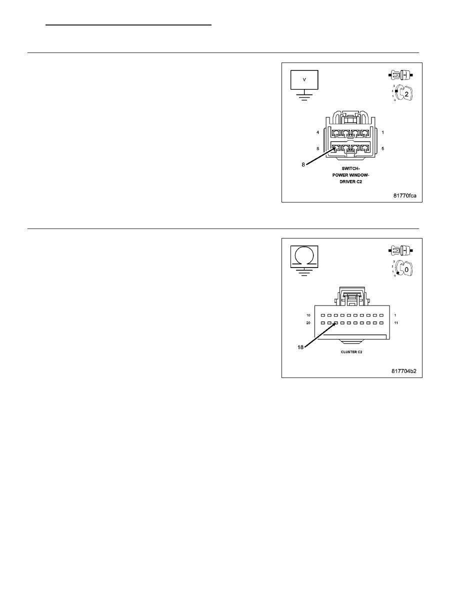
(P697) DRIVER DOOR LOCK SWITCH MUX CIRCUIT SHORT TO BATTERY

Ensure the ignition is on.

Measure the voltage between the (P697) Driver Door Lock Switch Mux
circuit and ground.

Is the voltage above 5.2 volts?

Yes

>> Repair the (P697) Left Door Lock Switch Mux circuit for a

short to battery.

Perform BODY VERIFICATION TEST - VER 1. (Refer to 8 -
ELECTRICAL/ELECTRONIC

CONTROL

MODULES

-

STANDARD PROCEDURE)

No

>> Go To 4

4.

(P697) DRIVER DOOR LOCK SWITCH MUX CIRCUIT SHORT TO GROUND

Turn the ignition off.

Disconnect the Cluster C2 connector.

Measure the resistance between ground and the (P697) Driver Door
Lock Switch Mux circuit.

Is the resistance below 1000.0 ohms?

Yes

>> Repair the (P697) Driver Door Lock Switch Mux circuit for a

short to ground.

Perform BODY VERIFICATION TEST - VER 1. (Refer to 8 -
ELECTRICAL/ELECTRONIC

CONTROL

MODULES

-

STANDARD PROCEDURE)

No

>> Go To 5

PM

POWER LOCKS - ELECTRICAL DIAGNOSTICS

8N - 5

5.

(P697) DRIVER DOOR LOCK SWITCH MUX CIRCUIT OPEN

Measure the resistance of the (P697) Driver Door Lock Switch Mux cir-
cuit between the Cluster C2 connector and the Driver Window/Door
Lock Switch connector.

Is the resistance below 5.0 ohms?

No

>> Repair the (P697) Driver Door Lock Switch Mux circuit for

an open.

Perform BODY VERIFICATION TEST - VER 1. (Refer to 8 -
ELECTRICAL/ELECTRONIC

CONTROL

MODULES

-

STANDARD PROCEDURE)

Yes

>> Replace the Instrument Cluster in accordance with service

information.

Perform BODY VERIFICATION TEST - VER 1. (Refer to 8 -
ELECTRICAL/ELECTRONIC

CONTROL

MODULES

-

STANDARD PROCEDURE)

8N - 6

POWER LOCKS - ELECTRICAL DIAGNOSTICS

PM

B1801 DRIVER DOOR LOCK/UNLOCK SWITCH CIRCUIT LOW – CLUSTER

For a complete wiring diagram Refer to Section 8W.

PM

POWER LOCKS - ELECTRICAL DIAGNOSTICS

8N - 7

When Monitored:
Continuously

Set Condition:
When the Driver Door Lock Switch Mux circuit is below 0.15 volts for over 10 seconds.

Possible Causes

(P697) DRIVER DOOR LOCK SWITCH MUX CIRCUIT SHORT TO GROUND

DOOR LOCK SWITCH SHORT TO GROUND

INSTRUMENT CLUSTER

Diagnostic Test

1.

TEST FOR INTERMITTENT CONDITION

With the scan tool, record and erase DTC’s

Operate the Driver Door Lock Switch in all positions several times.

Cycle the ignition from on to off.

Turn the ignition on.

With the scan tool, read DTC’s.

Does the scan tool display B1801–DRIVER DOOR LOCK/UNLOCK SWITCH CIRCUIT LOW?

Yes

>> Go To 2

No

>> The conditions that caused this code to set are not present at this time. Using the wiring diagram/sche-

matic as a guide, inspect the wiring and connectors.

Perform BODY VERIFICATION TEST - VER 1. (Refer to 8 - ELECTRICAL/ELECTRONIC CONTROL
MODULES - STANDARD PROCEDURE)

2.

DOOR LOCK SWITCH SHORTED

With the scan tool, erase DTC’s.

Disconnect the Driver Window/Door Lock Switch connector.

With the scan tool, read DTC’s.

Does the scan tool display B1801–DRIVER DOOR LOCK/UN-
LOCK SWITCH CIRCUIT LOW?

No

>> Replace the Driver Window/Door Lock Switch.

Perform BODY VERIFICATION TEST - VER 1. (Refer to 8 -
ELECTRICAL/ELECTRONIC

CONTROL

MODULES

-

STANDARD PROCEDURE)

Yes

>> Go To 3

8N - 8

POWER LOCKS - ELECTRICAL DIAGNOSTICS

PM


Content   ..  380  381  382  383   ..