Dodge Caliber. Manual - part 346
3.
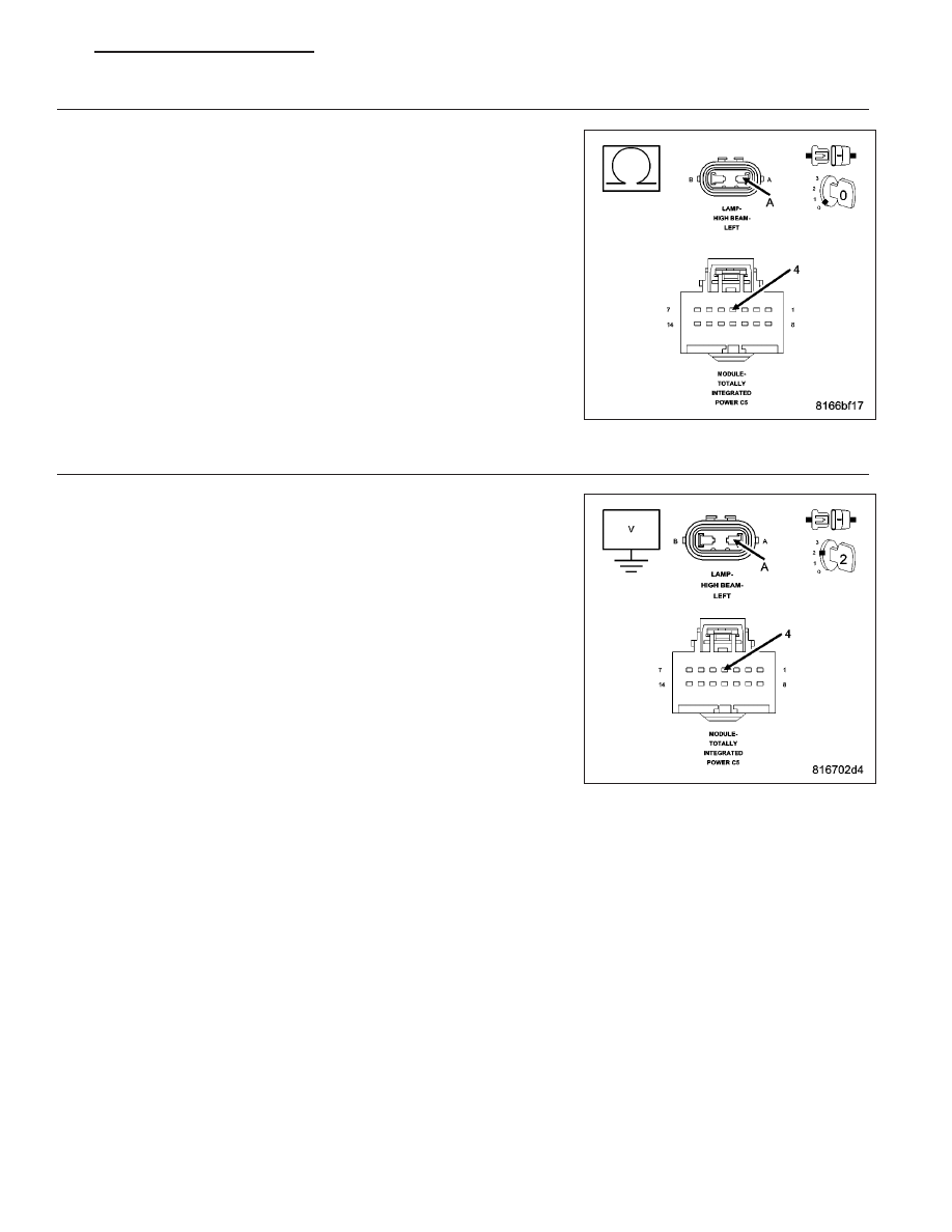
(L33) HIGH BEAM CONTROL CIRCUIT
Turn the ignition off.
Disconnect the TIPM C5 harness connector.
Disconnect the Left High Beam Lamp harness connector.
Measure the resistance of the (L33) High Beam Control circuit.
Is the resistance above 5.0 ohms?
Yes
>> Repair the (L33) High Beam Control circuit for an open con-
dition.
Perform the BODY VERIFICATION TEST - VER 1. (Refer to
8 - ELECTRICAL/ELECTRONIC CONTROL MODULES -
STANDARD PROCEDURE)
No
>> Go To 4
4.
(L33) HIGH BEAM CONTROL CIRCUIT SHORT TO VOLTAGE
Turn the ignition off.
Disconnect the TIPM C5 harness connector.
Disconnect the Left High Beam Lamp harness connector.
Turn the ignition on.
Measure for voltage on the (L33) High Beam Control circuit.
Is the voltage above 10.0 volts?
Yes
>> Repair the (L33) High Beam Control circuit for a short to
voltage condition.
Perform the BODY VERIFICATION TEST - VER 1. (Refer to
8 - ELECTRICAL/ELECTRONIC CONTROL MODULES -
STANDARD PROCEDURE)
No
>> Replace the Totally Integrated Power Module (TIPM) in
accordance with the service information.
Perform the BODY VERIFICATION TEST - VER 1. (Refer to
8 - ELECTRICAL/ELECTRONIC CONTROL MODULES -
STANDARD PROCEDURE)
PM
LAMPS/LIGHTING - EXTERIOR - ELECTRICAL DIAGNOSTICS
8L - 17