Dodge Caliber. Manual - part 251


  Index      Dodge     Dodge Caliber - service repair manual 2007 year


Search            


Content   ..  249  250  251  252   ..


Dodge Caliber. Manual - part 251


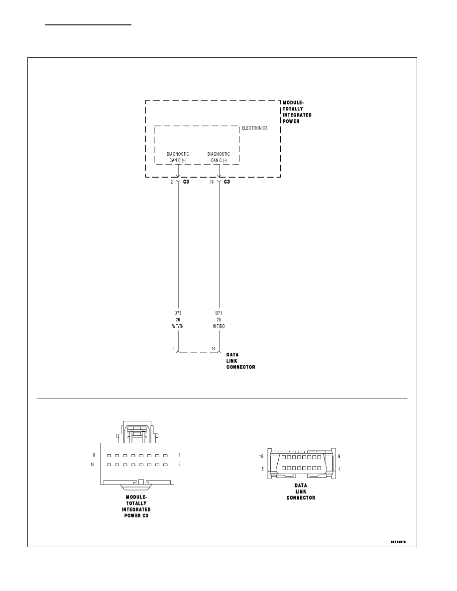
*BOTH DIAGNOSTIC CAN C (+) AND DIAGNOSTIC CAN C (-) CIRCUITS OPEN

For a complete wiring diagram Refer to Section 8W.

PM

ELECTRONIC CONTROL MODULES - ELECTRICAL DIAGNOSTICS

8E - 115

When Monitored:
When the scan tool queries the TIPM.

Set Condition:
The scan tool has detected an open condition on both Diagnostic CAN C circuits.

Possible Causes

(D72) DIAGNOSTIC CAN C (+) CIRCUIT OPEN

(D71) DIAGNOSTIC CAN C (-) CIRCUIT OPEN

TOTALLY INTEGRATED POWER MODULE

Diagnostic Test

1.

CHECK THE STATUS OF THE ERROR MESSAGE

NOTE: Ensure the vehicle being tested is a CAN BUS VEHICLE. If not, false error messages may be dis-
played.

NOTE: Ensure the scan tool is updated to the latest software.
With the scan tool, record the error message.

Disconnect the scan tool from the DLC.

Cycle the ignition from on to off 3 times.

Turn the ignition on.

Does the scan tool display this same error message?

Yes

>> Go To 2

No

>> The conditions that caused this error message to set are not present at this time. Using the wiring dia-

gram/schematic as a guide, inspect the wiring and connectors.

2.

(D72) CAN C DIAGNOSTIC (+) CIRCUIT OPEN

Turn the ignition off.

Disconnect the TIPM C3 harness connector.

Disconnect the scan tool from the DLC.

NOTE: Check the connectors at both the DLC and the TIPM.
Measure the resistance of the (D72) Diagnostic CAN C (+) circuit
between the TIPM connector and the DLC.

Is the resistance below 5.0 ohms?

Yes

>> Go To 3

No

>> Repair the (D72) Diagnostic CAN C (+) circuit for an open.

Perform BODY VERIFICATION TEST – VER 1. (Refer to 8
-

ELECTRICAL/ELECTRONIC

CONTROL MODULES

-

STANDARD PROCEDURE).

8E - 116

ELECTRONIC CONTROL MODULES - ELECTRICAL DIAGNOSTICS

PM

3.

(D71) DIAGNOSTIC CAN C (-) CIRCUIT OPEN

Measure the resistance of the (D71) Diagnostic CAN C (-) circuit
between the TIPM C3 harness connector and the DLC.

Is the resistance below 5.0 ohms?

Yes

>> Inspect the wiring and connectors for damage or shorted

circuits. If ok, replace the Totally Integrated Power Module
in accordance with the service information.

Perform the BODY VERIFICATION TEST – VER 1. (Refer
to 8 - ELECTRICAL/ELECTRONIC CONTROL MODULES -
STANDARD PROCEDURE).

No

>> Repair the (D71) Diagnostic CAN C (-) circuit for an open.

Perform the BODY VERIFICATION TEST – VER 1. (Refer
to 8 - ELECTRICAL/ELECTRONIC CONTROL MODULES -
STANDARD PROCEDURE).

PM

ELECTRONIC CONTROL MODULES - ELECTRICAL DIAGNOSTICS

8E - 117

*NO RESPONSE FROM ABS (ANTILOCK BRAKE MODULE)

For a complete wiring diagram Refer to Section 8W.

8E - 118

ELECTRONIC CONTROL MODULES - ELECTRICAL DIAGNOSTICS

PM


Content   ..  249  250  251  252   ..