Dodge Caliber. Manual - part 231


  Index      Dodge     Dodge Caliber - service repair manual 2007 year


Search            


Content   ..  229  230  231  232   ..


Dodge Caliber. Manual - part 231


3.

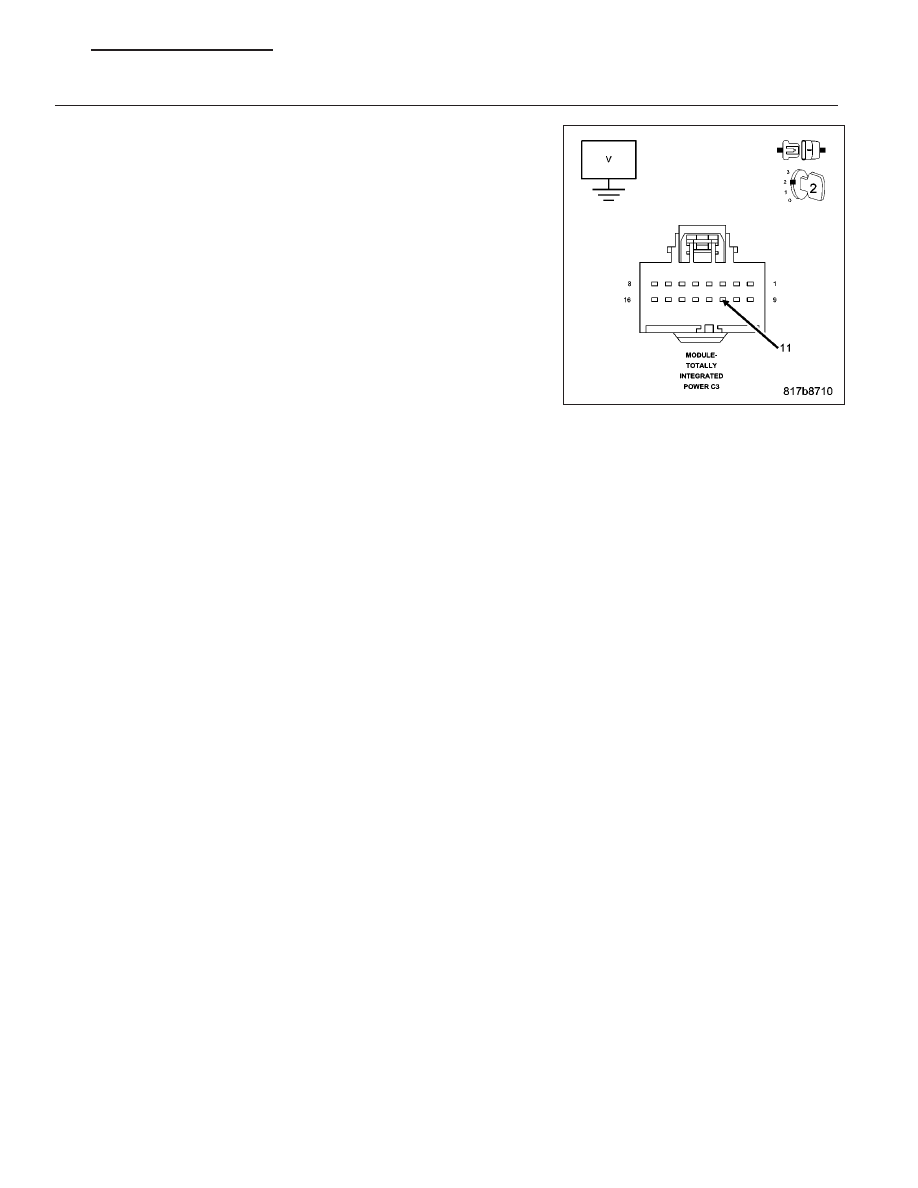
(D54) CAN B BUS (-) CIRCUIT SHORTED TO VOLTAGE

Measure the voltage between the (D54) CAN B Bus (-) circuit and
ground.

While monitoring the voltmeter, disconnect each CAN B Bus module
one at a time.

NOTE: When performing the above step, turn the ignition off (wait
one minute) before disconnecting any module. When the module is
disconnected turn the ignition on to check for a short to voltage.

NOTE: This is to determine if the circuit is shorted to voltage inter-
nally within a module or if the circuit is shorted to voltage in the
harness.

NOTE: Disconnecting an in-line connector can eliminate a module
or group of modules from the list of possible causes for this fault.
Refer to the wring diagrams to assist in diagnosis.

Is the voltage above 10.0 volts with all the CAN B Bus mod-
ules disconnected?

Yes

>> Repair the (D54) CAN B Bus (-) circuit for a short to volt-

age.

Perform the BODY VERIFICATION TEST – VER 1. (Refer to 8 - ELECTRICAL/ELECTRONIC CON-
TROL MODULES - STANDARD PROCEDURE).

No

>> Replace the module, in accordance with the service information, that when disconnected eliminated the

short to voltage.

Perform the BODY VERIFICATION TEST – VER 1. (Refer to 8 - ELECTRICAL/ELECTRONIC CON-
TROL MODULES - STANDARD PROCEDURE).

PM

ELECTRONIC CONTROL MODULES - ELECTRICAL DIAGNOSTICS

8E - 35

U0027-CAN B BUS (-) SHORTED TO BUS (+)

For a complete wiring diagram Refer to Section 8W.

8E - 36

ELECTRONIC CONTROL MODULES - ELECTRICAL DIAGNOSTICS

PM

When Monitored:
Continuously.

Set Condition:
The TIPM detects the (D55) CAN B Bus (+) circuit is shorted to the (D54) CAN B Bus (-) circuit.

Possible Causes

(D55) CAN B BUS (+) CIRCUIT SHORTED TO THE (D54) CAN B BUS (-) CIRCUIT

ANY CAN B BUS MODULE

TOTALLY INTEGRATED POWER MODULE

Diagnostic Test

1.

TEST FOR INTERMITTENT CONDITION

Turn the ignition on.

With the scan tool, record and erase TIPM DTC’s.

Cycle the ignition from on to off 3 times.

Turn the ignition on.

With the scan tool, read active TIPM DTC’s.

Does the scan tool display this DTC as active?

Yes

>> Go To 2

No

>> The conditions that caused this code to set are not present at this time. Using the wiring diagram/sche-

matic as a guide, inspect the wiring and connectors.

2.

CHECK THE (D55) CAN B BUS (+) CIRCUIT FOR A SHORT TO THE (D54) CAN B BUS (-) CIRCUIT

Turn the ignition off.

Disconnect the Totally Integrated Power Module C3 harness connector.

Measure the resistance between the (D55) CAN B Bus (+) circuit and
(D54) CAN B Bus (-) circuit.

Is resistance below 1000.0 ohms?

Yes

>> Go To 3

No

>> Inspect the wiring and connectors for damage or shorted

circuits. If ok, replace the Totally Integrated Power Module
in accordance with the service information.

Perform the BODY VERIFICATION TEST – VER 1. (Refer
to 8 - ELECTRICAL/ELECTRONIC CONTROL MODULES -
STANDARD PROCEDURE).

PM

ELECTRONIC CONTROL MODULES - ELECTRICAL DIAGNOSTICS

8E - 37

3.

(D55) CAN B BUS (+) CIRCUIT SHORTED TO THE (D54) CAN B BUS (-) CIRCUIT

Measure the resistance between the (D55) CAN B Bus (+) circuit and
(D54) CAN B Bus (-) circuit.

While monitoring the ohmmeter, disconnect each CAN B Bus module
one at a time.

NOTE: This is to determine if the circuits are shorted together
internally within a module or if the circuits are shorted together in
the harness.

NOTE: Disconnecting an in-line connector can eliminate a module
or group of modules from the list of possible causes for this fault.
Refer to the wring diagrams to assist in diagnosis.

Is resistance below 1000.0 ohms with all the CAN B Bus mod-
ules disconnected?

Yes

>> Repair the (D55) CAN B Bus (+) circuit for a short to the

(D54) CAN B Bus (-) circuit.

Perform the BODY VERIFICATION TEST – VER 1. (Refer
to 8 - ELECTRICAL/ELECTRONIC CONTROL MODULES -
STANDARD PROCEDURE).

No

>> Replace the module, in accordance with the service information, that when disconnected eliminated the

shorted together circuits.

Perform the BODY VERIFICATION TEST – VER 1. (Refer to 8 - ELECTRICAL/ELECTRONIC CON-
TROL MODULES - STANDARD PROCEDURE).

8E - 38

ELECTRONIC CONTROL MODULES - ELECTRICAL DIAGNOSTICS

PM


Content   ..  229  230  231  232   ..