Dodge Caliber. Manual - part 213


  Index      Dodge     Dodge Caliber - service repair manual 2007 year


Search            


Content   ..  211  212  213  214   ..


Dodge Caliber. Manual - part 213


AMPLIFIER

DESCRIPTION

The optional premium speaker system includes a separate audio power amplifier. The amplifier is located on the
floor behind the spare tire in the trunk.

OPERATION

The power amplifier electronically increases the frequency response of the normal audio signal output from the radio
amplifier in order to improve the acoustic performance of the speakers. On vehicles equipped with an amplifier, the
amplifier section of the radio becomes a pre-amplifier.

The amplifier receives audio signal inputs for speaker channels from the radio, then sends amplified audio outputs
with dedicated feed and return circuits to the individual speakers.
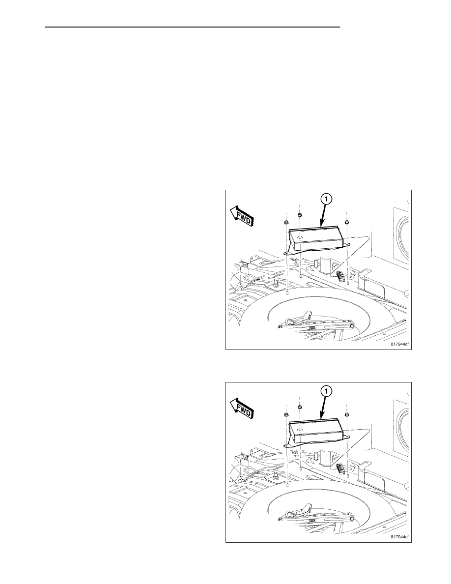
REMOVAL

1. Disconnect and isolate the battery negative cable.

2. Remove the retaining fasteners.

3. Disconnect the wire harness connector.

4. Remove the amplifier (1).

INSTALLATION

1. Install amplifier (1).

2. Install the mounting fasteners.

3. Connect wire harness connector to amplifier.

4. Connect battery negative cable.

PM

AUDIO

8A - 125

ANTENNA BODY AND CABLE

DESCRIPTION – Fixed Mast Antenna

The antenna body and cable are secured below the fender panel by the antenna cap nut through a mounting hole
in the side of the right front fender. The primary coaxial antenna cable is then routed beneath the fender sheet metal
and through an entry hole in the right cowl side panel into the interior of the vehicle. Inside the vehicle, the primary
coaxial cable is connected to a secondary instrument panel antenna coaxial cable with an in-line connector that is
located behind the right end of the instrument panel. The secondary coaxial cable is then routed behind the instru-
ment panel to the back of the radio.

DESCRIPTION – Roof Mounted Antenna

The roof mounted antenna is a combination antenna that is used for the reception of Amplitude Modulation (AM)
frequencies, Frequency Modulated (FM) frequencies and Satellite signals for the Digital Satellite Radio. The primary
coaxial antenna cable is then routed through an entry hole in the roof panel into the interior of the vehicle. Inside the
vehicle, the primary coaxial cable is connected to a secondary instrument panel antenna coaxial cable with an in-
line connector that is located behind the right end of the instrument panel. The secondary coaxial cable is then
routed behind the instrument panel to the back of the radio.

OPERATION

The antenna body and cable connects the antenna mast to the radio. The radio antenna is an electromagnetic
circuit component used to capture radio frequency signals that are broadcast by local commercial radio stations in
both the Amplitude Modulating (AM) and Frequency Modulating (FM) frequency ranges. These electromagnetic radio
frequency signals induce small electrical modulations into the antenna as they move past the mast. The antenna
body transfers the weak electromagnetic radio waves induced into the rigid antenna mast into the center conductor
of the flexible primary antenna coaxial cable. The braided outer shield of the antenna coaxial cable is grounded
through both the antenna body and the radio chassis, effectively shielding the radio waves as they are conducted to
the radio. The radio then tunes and amplifies the weak radio signals into stronger electrical signals in order to oper-
ate the audio system speakers. For more information on the satellite radio operation of the roof mounted antenna,
Refer to (Refer to 8 - ELECTRICAL/AUDIO/ANTENNA MAST - OPERATION)

DIAGNOSIS AND TESTING - ANTENNA BODY AND CABLE

The following four tests are used to diagnose the antenna with an ohmmeter:

TEST 1 - Mast to ground test

TEST 2 - Tip-of-mast to tip-of-conductor test

TEST 3 - Body ground to battery ground test

TEST 4 - Body ground to antenna coaxial cable shield test.

WARNING: Disable the airbag system before attempting any steering wheel, steering column, seat belt ten-
sioner, side airbag, or instrument panel component diagnosis or service. Disconnect and isolate the battery
negative (ground) cable, then wait two minutes for the airbag system capacitor to discharge before per-
forming further diagnosis or service. This is the only sure way to disable the airbag system. Failure to take
the proper precautions could result in accidental airbag deployment and possible personal injury.

The ohmmeter test lead connections for each test are shown in the illustration.

8A - 126

AUDIO

PM

NOTE: This model has a two-piece antenna coaxial cable. Tests 2 and 4 must be conducted in two steps to
isolate an antenna cable problem. First, test the primary antenna cable (integral to the antenna body and
cable) from the coaxial cable connector under the right end of the instrument panel near the right cowl side
inner panel to the antenna body. Then, test the secondary antenna cable (instrument panel antenna cable)
from the coaxial cable connector under the right end of the instrument panel near the right cowl side inner
panel to the coaxial cable connector at the radio.

TEST 1

Test 1 determines if the antenna mast is insulated
from ground. Proceed as follows:

1. Disconnect and isolate the antenna coaxial cable

connector under the right end of the instrument
panel near the right cowl side inner panel.

2. Touch one ohmmeter test lead to the tip of the

antenna mast (below tip if ball tip is plastic). Touch
the other test lead to the antenna cap nut. Check
the ohmmeter reading for continuity.

3. There should be no continuity. If OK, go to Test 2.

If not OK, replace the faulty antenna body and
cable.

TEST 2

Test 2 checks the antenna conductor components for an open circuit. This test should be performed first on the
entire antenna circuit, from the antenna mast to the center conductor of the coaxial cable connector at the radio. If
an open circuit is detected, each of the three antenna conductor components (antenna mast, antenna body and
primary cable unit, instrument panel antenna secondary cable) should be isolated and tested individually to locate
the exact component that is the source of the open circuit. To begin this test, proceed as follows:

1. Disconnect the instrument panel (secondary) antenna cable coaxial connector from the back of the radio.

2. Touch one ohmmeter test lead to the tip of the antenna mast. Touch the other test lead to the center conductor

pin of the instrument panel antenna cable coaxial connector for the radio. Check the ohmmeter reading for con-
tinuity.

3. There should be continuity. The ohmmeter should register only a fraction of an ohm resistance. High or infinite

resistance indicates a damaged or open antenna conductor. If OK, go to Test 3. If not OK, isolate and test each
of the individual antenna conductor components. Replace only the faulty antenna conductor component.

TEST 3

Test 3 checks the condition of the vehicle body ground connection. To begin this test, proceed as follows:

1. This test must be performed with the battery positive cable disconnected from the battery. Disconnect and isolate

both battery cables, negative cable first.

2. Reconnect the battery negative cable.

3. Touch one ohmmeter test lead to a good clean ground point on the vehicle fender. Touch the other test lead to

the battery negative terminal post. Check the ohmmeter reading for continuity.

4. There should be continuity. The ohmmeter should register less than one ohm resistance. High or infinite resis-

tance indicates a loose, corroded, or damaged connection between the battery negative terminal and the vehicle
body. If OK, go to Test 4. If not OK, check the battery negative cable connection to the vehicle body and the
radio noise suppression ground strap connections to the engine and the vehicle body for being loose or cor-
roded. Clean or tighten these connections as required.

PM

AUDIO

8A - 127

TEST 4

Test 4 checks the condition of the connection between the antenna coaxial cable shield and the vehicle body ground
as follows:

1. Disconnect and isolate the antenna coaxial cable connector under the right end of the instrument panel near the

right cowl side inner panel.

2. Touch one ohmmeter test lead to a good clean ground point on the vehicle fender. Touch the other test lead to

the outer crimp on the antenna coaxial cable connector under the right end of the instrument panel near the right
cowl side inner panel. Check the ohmmeter reading for continuity.

3. There should be continuity. The ohmmeter should register less than one ohm resistance. High or infinite resis-

tance indicates a loose, corroded, or damaged connection between the antenna body and the vehicle body or
between the antenna body and the antenna coaxial cable shield. If not OK, clean the antenna body to fender
mating surfaces and tighten the antenna cap nut to specifications.

4. Check the resistance again with an ohmmeter. If the resistance is still more then one ohm, replace the faulty

antenna body and cable.

REMOVAL

1. Disconnect and isolate the battery negative cable.

2. Remove antenna mast by unscrewing mast from

antenna body. On vehicles equipped with manual
retractable antenna, lower antenna fully.

3. Remove shroud (1), if equipped.

4. Remove antenna nut (2) and adapter (3)

5. Disconnect antenna body cable from instrument

panel antenna cable.

6. Remove inner fender shield as necessary to gain

access to mounting fasteners.

7. Remove antenna body and cable (2) assembly

from fender (1)

8A - 128

AUDIO

PM


Content   ..  211  212  213  214   ..