Dodge Caliber. Manual - part 178


  Index      Dodge     Dodge Caliber - service repair manual 2007 year


Search            


Content   ..  176  177  178  179   ..


Dodge Caliber. Manual - part 178


CAP RADIATOR PRESSURE

DESCRIPTION

GAS ENGINES

The cooling system is equipped with a pressure cap
that releases built up pressure, maintaining a range of
97-124 kPa (14-18 psi).

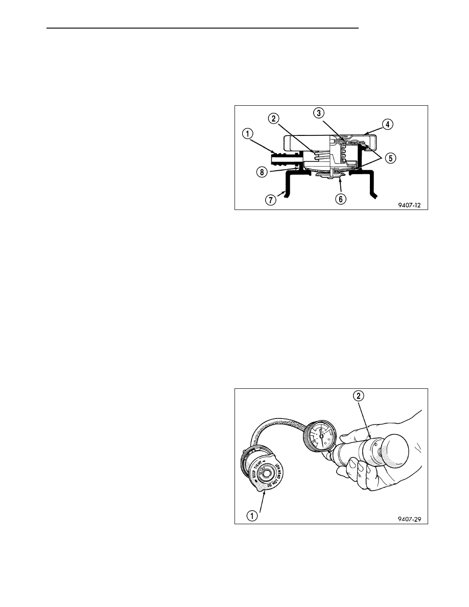
There is also a vent valve (6) in the center of the cap.
This valve also opens when coolant is cooling and
contracting, allowing coolant to return to radiator from
coolant recovery container by vacuum through con-
necting hose. If valve is stuck shut, the radiator
hoses will be collapsed on cool down. Clean the
vent valve to ensure proper sealing when boiling
point is reached.

OPERATION

GAS ENGINES

The pressure cap allows the cooling system to operate at higher than atmospheric pressure. The higher pressure
raises the coolant boiling point; this allows increased radiator cooling capacity.

The secondary gasket in the cap seals the filler neck and the primary gasket seals the cooling system so that
vacuum can be maintained, allowing coolant to be drawn back into the radiator from the reserve container.

A vent valve in the center of the cap will remain shut as long as the cooling system is pressurized. As the coolant
cools, it contracts and creates a vacuum in cooling system. This causes the vacuum valve to open and coolant in
reserve/overflow tank to be drawn through connecting hose into radiator. If the vacuum valve is stuck shut, or over-
flow hose is kinked, radiator hoses will collapse on cool-down.

DIAGNOSIS AND TESTING

DIAGNOSIS AND TESTING - COOLING SYSTEM PRESSURE CAP TESTING

Dip the pressure cap in water. Clean any deposits off
the vent valve or its seat and apply cap to end of the
Pressure Cap Test Adaptor that is included with the
Cooling System Tester 7700. Working the plunger,
bring the pressure to 104 kPa (15 psi) on the gauge. If
the pressure cap fails to hold pressure of at least 97
kPa (14 psi), replace the pressure cap.

CAUTION: The Cooling System Tester Tool is very
sensitive to small air leaks that will not cause
cooling system problems. A pressure cap that
does not have a history of coolant loss should not
be replaced just because it leaks slowly when
tested with this tool. Add water to the tool. Turn
tool upside down and recheck pressure cap to
confirm that cap is bad.

If the pressure cap tests properly while positioned on Cooling System Tester 7700, but will not hold pressure or
vacuum when positioned on the filler neck. Inspect the filler neck and cap top gasket for irregularities that may
prevent the cap from sealing properly.

PM

ENGINE

7 - 37

DIAGNOSIS AND TESTING - COOLING SYSTEM PRESSURE RELIEF TESTING

WARNING: IF VEHICLE HAS BEEN RUN RECENTLY, WAIT 15 MINUTES BEFORE REMOVING CAP. PLACE A
SHOP TOWEL OVER THE CAP, AND WITHOUT PUSHING DOWN, ROTATE IT COUNTERCLOCKWISE TO THE
FIRST STOP. ALLOW FLUIDS TO ESCAPE THROUGH THE OVERFLOW TUBE. WHEN THE SYSTEM STOPS
PUSHING COOLANT AND STEAM INTO THE COOLANT RECOVERY CONTAINER AND PRESSURE DROPS,
PUSH DOWN ON THE CAP AND REMOVE IT COMPLETELY. SQUEEZING THE RADIATOR INLET HOSE WITH
A SHOP TOWEL (TO CHECK PRESSURE) BEFORE AND AFTER TURNING TO THE FIRST STOP IS RECOM-
MENDED.

WARNING: THE WARNING WORDS “DO NOT OPEN HOT” ON THE PRESSURE CAP IS A SAFETY PRECAU-
TION. WHEN HOT, THE COOLING SYSTEM BUILDS UP PRESSURE. TO PREVENT SCALDING OR OTHER
INJURY, THE PRESSURE CAP SHOULD NOT BE REMOVED WHILE THE SYSTEM IS HOT AND/OR UNDER
PRESSURE.

The pressure cap upper gasket to filler neck seal can be checked by removing the overflow hose at the radiator
filler neck overflow nipple. Attach the radiator pressure tester to the filler neck overflow nipple, and pump air into
the system. The pressure cap upper gasket should relieve pressure at 69-124 kPa (10-18 psi), and hold pressure at
55 kPa (8 psi) minimum.

There is no need to remove the pressure cap at any time except for the following purposes:

Check and adjust coolant freeze point

Refill system with new coolant

Conducting service procedures

Checking for leaks

CLEANING

Use only a mild soap to clean the pressure cap.

INSPECTION

Hold the cap in your hand, top side up.. The vent
valve (6) at the bottom of the cap should open. If the
rubber seal (5) has swollen, preventing the valve from
opening, replace the cap.

Hold the cleaned cap in your hand, upside down. If
any light can be seen between vent valve (6) and the
rubber seal (5), replace the cap. Do not use a
replacement cap that has a spring to hold the vent
shut.

A replacement cap must be of the type designed for a
full pressure coolant systems. This design ensures
coolant return to the radiator.

7 - 38

ENGINE

PM

DRAINCOCK RADIATOR

REMOVAL

CAUTION: Use of pliers on draincock is not rec-
ommended. Damage may occur to radiator or
draincock.

NOTE: It is not necessary to remove draincock
during a routine coolant drain.

1. Drain the cooling system (Refer to 7 - COOLING/

ENGINE - STANDARD PROCEDURE).

2. Open the draincock (2) by turning it counterclock-

wise until it stops.

3. Turn the draincock (2) back (clockwise) 1/8 turn.

4. Pull the draincock (2) from the radiator tank (1).

INSTALLATION

1. Align draincock stem to radiator tank opening.

2. Push draincock (2) into the radiator tank opening.

3. Tighten the draincock (2) by turning clockwise until

it stops.

4. Fill the cooling system (Refer to 7 - COOLING/EN-

GINE - STANDARD PROCEDURE).

PM

ENGINE

7 - 39

FAN-RADIATOR

DESCRIPTION

The radiator cooling fans are dual-speed electric motor driven fans. The radiator fan assembly includes two electric
motors, two five blade fans, and a support shroud that is attached to the radiator. The radiator fans are serviced as
an assembly.

OPERATION

Radiator fan operation is controled by the Totally Integrated Power Module (TIPM), with inputs from the temperature
of the coolant, which is sensed by the coolant temperature sensor, and vehicle speed which is measured by the
vehicle speed sensor. The (TIPM) turns on the fan through either the high or low speed fan relay. The PCM pro-
vides a ground to the relay’s control circuit. The fan relays are located in the (TIPM). Refer to the label beneath
the(TIPM) cover for location of fan relays.

Refer to Radiator Fan Operation Chart for fan operation specifications. For fan circuit wiring diagrams, refer to
WIRING DIAGRAMS.

If the cooling fan is inoperative or a Diagnostic Trouble Code (DTC) related to fan control has been set, refer to the
appropriate Powertrain Diagnostic Information for diagnostic procedures.

RADIATOR FAN OPERATION CHART

Radiator Fan Control

Low Speed

High Speed

A/C Off –vehicle speed < 70.8 km/h (44 mph)

Fan On:

96.6° C (206° F)

103° C (219° F)

Fan Off:

92.7° C (199° F)

98.8° C (210° F)

A/C Off –vehicle speed > 70.8 km/h (44 mph) (until vehicle speed drops below 58 km/h (36 mph)

Fan On:

Off

103° C (219° F)

Fan Off:

98.8° C (210° F)

A/C On –any vehicle speed

Fan On:

Off

82.2° C (180° F)

Fan Off:

80° C (176° F)

DIAGNOSIS AND TESTING

RADIATOR FAN

(Refer to Appropriate Diagnostic Information)

7 - 40

ENGINE

PM


Content   ..  176  177  178  179   ..