Dodge Caliber. Manual - part 160


  Index      Dodge     Dodge Caliber - service repair manual 2007 year


Search            


Content   ..  158  159  160  161   ..


Dodge Caliber. Manual - part 160


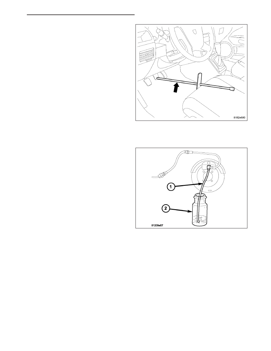
15. Remove brake pedal holding tool.

16. Install the engine appearance cover.

17. Connect the battery negative cable to the battery post. It is important that this be performed properly. (Refer to

8 - ELECTRICAL/BATTERY SYSTEM - STANDARD PROCEDURE)

18. Hook up the scan tool to initialize the ABM and

perform the following:

a. Clear any faults.

b. Fill the master cylinder to the proper fill level

and bleed the base and ABS hydraulic sys-
tems. (Refer to 5 - BRAKES - ABS - STAN-
DARD PROCEDURE)

c. Perform the ABS Verification Test and road test

the vehicle.

PM

BRAKES - ABS SERVICE INFORMATION

5 - 341

CLUTCH

TABLE OF CONTENTS

page

page

CLUTCH

DESCRIPTION . . . . . . . . . . . . . . . . . . . . . . . . . . . . . . . . . 2
OPERATION . . . . . . . . . . . . . . . . . . . . . . . . . . . . . . . . . . . 2
DIAGNOSIS AND TESTING

CLUTCH SYSTEM . . . . . . . . . . . . . . . . . . . . . . . . . . . 3
CLUTCH CHATTER COMPLAINTS . . . . . . . . . . . . . 5
DRIVE PLATE MISALIGNMENT . . . . . . . . . . . . . . . . 5
CLASH-INTO-REVERSE COMPLAINTS . . . . . . . . 5

STANDARD PROCEDURE

GRAVITY BLEEDING CLUTCH HYDRAULIC

CIRCUIT . . . . . . . . . . . . . . . . . . . . . . . . . . . . . . . . . . . 6

SPECIFICATIONS

CLUTCH/HYDRAULICS/PEDALS . . . . . . . . . . . . . . 7

SPECIAL TOOLS

HYDRAULIC CLUTCH . . . . . . . . . . . . . . . . . . . . . . . . 9

PLATE-CLUTCH DISC AND PRESSURE

REMOVAL . . . . . . . . . . . . . . . . . . . . . . . . . . . . . . . . . . . . 10
INSTALLATION . . . . . . . . . . . . . . . . . . . . . . . . . . . . . . . . 11

FLYWHEEL

OPERATION . . . . . . . . . . . . . . . . . . . . . . . . . . . . . . . . . . 14
REMOVAL . . . . . . . . . . . . . . . . . . . . . . . . . . . . . . . . . . . . 14
INSTALLATION . . . . . . . . . . . . . . . . . . . . . . . . . . . . . . . 15

CYLINDER-MASTER-LHD

DESCRIPTION . . . . . . . . . . . . . . . . . . . . . . . . . . . . . . . . 16
OPERATION . . . . . . . . . . . . . . . . . . . . . . . . . . . . . . . . . . 17
REMOVAL . . . . . . . . . . . . . . . . . . . . . . . . . . . . . . . . . . . . 17
INSTALLATION . . . . . . . . . . . . . . . . . . . . . . . . . . . . . . . 19

CYLINDER-MASTER-RHD

DESCRIPTION . . . . . . . . . . . . . . . . . . . . . . . . . . . . . . . . 22
OPERATION . . . . . . . . . . . . . . . . . . . . . . . . . . . . . . . . . . 22
REMOVAL . . . . . . . . . . . . . . . . . . . . . . . . . . . . . . . . . . . . 22
INSTALLATION . . . . . . . . . . . . . . . . . . . . . . . . . . . . . . . 25

CLUTCH-MODULAR

DESCRIPTION . . . . . . . . . . . . . . . . . . . . . . . . . . . . . . . . 28
OPERATION . . . . . . . . . . . . . . . . . . . . . . . . . . . . . . . . . . 28
REMOVAL . . . . . . . . . . . . . . . . . . . . . . . . . . . . . . . . . . . . 29
INSPECTION . . . . . . . . . . . . . . . . . . . . . . . . . . . . . . . . . 30
INSTALLATION . . . . . . . . . . . . . . . . . . . . . . . . . . . . . . . 31

CYLINDER-SLAVE

DESCRIPTION . . . . . . . . . . . . . . . . . . . . . . . . . . . . . . . . 32
REMOVAL

Removal . . . . . . . . . . . . . . . . . . . . . . . . . . . . . . . . . . . 33

INSTALLATION . . . . . . . . . . . . . . . . . . . . . . . . . . . . . . . 34

PM

CLUTCH

6 - 1

CLUTCH

DESCRIPTION

The typical clutch hydraulic system consists of a
clutch master cylinder (2), slave cylinder (5), and an
interconnecting fluid line. Clutch hydraulic fluid is sup-
plied by the brake system via the brake master cylin-
der reservoir (1). The clutch pedal pushrod (4) is
adjustable.

On some models, the slave cylinder is integrated with
the clutch release bearing.

FLUID

CAUTION: Never use any type of petroleum-based fluid (engine oil, transmission oil, power steering fluid,
etc.) in the clutch hydraulic system. Use of such fluids will result in master/slave cylinder seal damage, and
cause a failure of the hydraulic clutch release system.

NOTE: Under normal operating conditions, the clutch hydraulic system does not require additional fluid for
the life of the vehicle. Since the clutch shares the brake reservoir, the fluid level will be maintained when-
ever the brake system is checked.

The fluid required for use in the clutch hydraulic system is brake fluid conforming to DOT 3 specifications and J1703
standards. No other type of fluid is recommended or approved for use in the clutch hydraulic system. Use only
MOPAR

T

brake fluid or equivalent from a tightly sealed container.

OPERATION

The clutch hydraulic system is responsible for engaging and disengaging the clutch. Depressing the clutch pedal
develops fluid pressure in the clutch master cylinder. This pressure is transmitted to the slave cylinder through a
connecting line.

Slave cylinder force transmits through the integral release bearing, which is in contact with the pressure plate dia-
phragm spring. As additional force is applied, the bearing depresses the diaphragm spring fingers inward on the
fulcrums. The action moves the pressure plate rearward, relieving clamping force on the clutch disc.

6 - 2

CLUTCH

PM


Content   ..  158  159  160  161   ..