Dodge Caliber. Manual - part 157


  Index      Dodge     Dodge Caliber - service repair manual 2007 year


Search            


Content   ..  155  156  157  158   ..


Dodge Caliber. Manual - part 157


4. Loosen, but do not remove, the two mounting

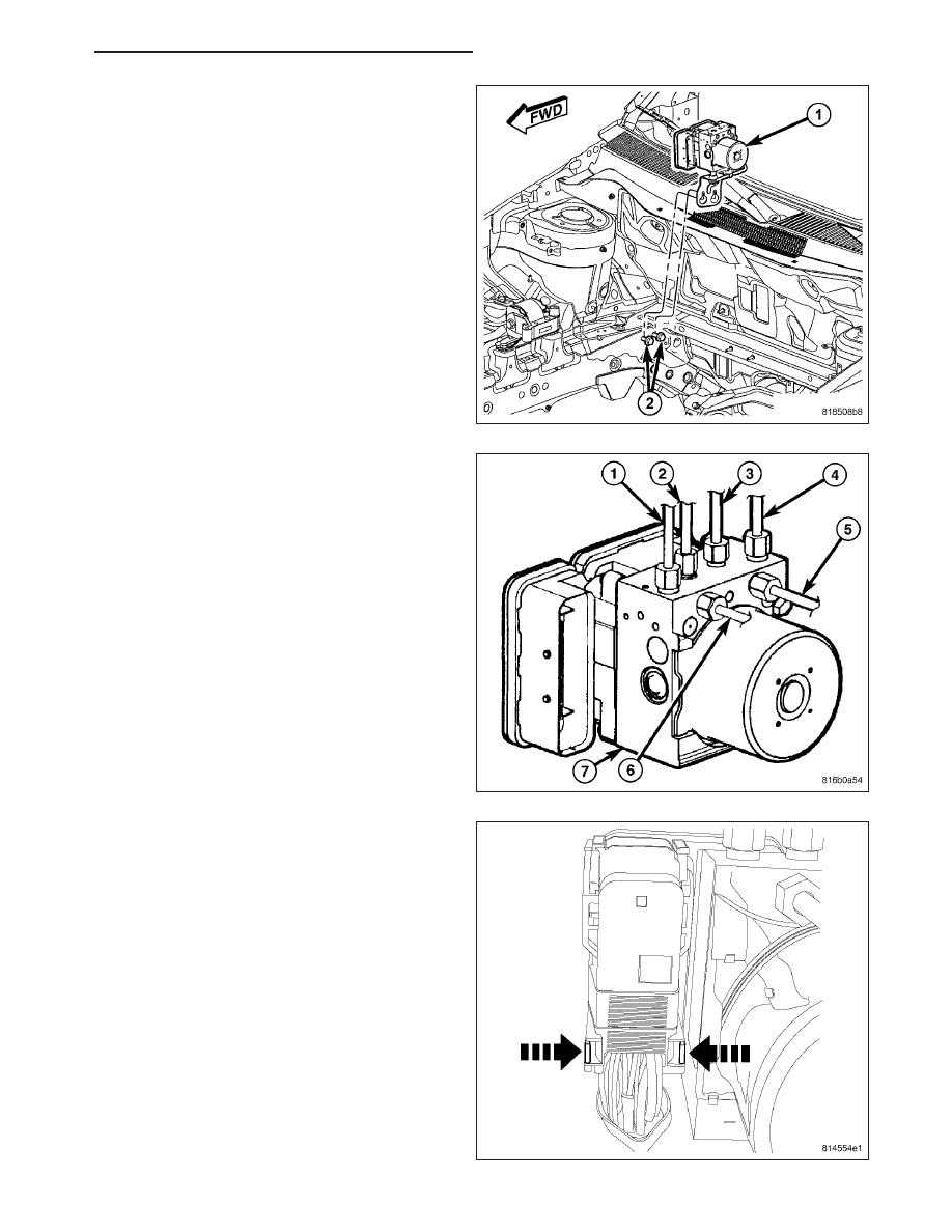
screws (2) attaching the ICU (1) mounting bracket
to the body.

5. Loosen the air inlet tube at the turbocharger.

6. Lower the vehicle.

7. Remove the engine appearance cover.

8. Loosen the air inlet tube at the air cleaner and

engine cylinder head cover, then remove the tube.

9. Loosen lower and upper mounting nuts, then

remove the heat shield from the dash panel.

10. Pull the brake tube bundle routing clips (with

tubes) loose from studs on the dash panel.

11. Remove primary (4) and secondary (1) brake

tubes (from master cylinder) at hydraulic control
unit (7).

12. Remove remaining brake tubes (2, 3, 5, 6) at

hydraulic control unit (7).

NOTE: Use this figure in the following step to
release the ABM harness connector cover. It
shows the location of the release tabs.

PM

BRAKES - ABS SERVICE INFORMATION

5 - 329

13. Disconnect the ABM harness connector from the

Antilock Brake Module (ABM). To do so:

a. Depress the tabs on each side of the connec-

tor cover, then

b. Pull outward and upward on the lower half of

the cover until it locks into position pointing
straight outward (2). The connector can then
be pulled straight outward off the ABM (1).

14. Lift the ICU and mounting bracket (1) off the

mounting screws (2).

15. Rotate the ICU (1) around behind the engine until

the bracket mounting screw (3) can be accessed.

16. Remove the ICU bracket mounting screw (3), then

remove the bracket (2) from the ICU (1). The ICU
has mounting pins that are inserted into grommets
in the bracket that must be overcome to remove
bracket.

5 - 330

BRAKES - ABS SERVICE INFORMATION

PM

17. Remove the ICU (1) from the engine compartment

out over the engine cylinder head cover (2).

18. To separate the ABM from the HCU, (Refer to 5 -

BRAKES/HYDRAULIC/MECHANICAL/ICU (INTE-
GRATED CONTROL UNIT) - DISASSEMBLY).

DISASSEMBLY

1. If the mounting bracket (3) needs to be removed

from the ICU, remove the single mounting bolt (2),
then slide the ICU’s mounting pins out of the grom-
mets in the bracket and remove the bracket.

PM

BRAKES - ABS SERVICE INFORMATION

5 - 331

2. Remove the mounting pins from the ICU.

3. If not equipped with traction control, remove the

three screws (1) attaching the ABM (2) to the HCU.

4. If equipped with traction control or ESP, remove the

four screws (1) attaching the ABM (2) to the HCU.

5 - 332

BRAKES - ABS SERVICE INFORMATION

PM


Content   ..  155  156  157  158   ..