Content .. 1435 1436 1437 1438 ..
Dodge Caliber. Manual - part 1437
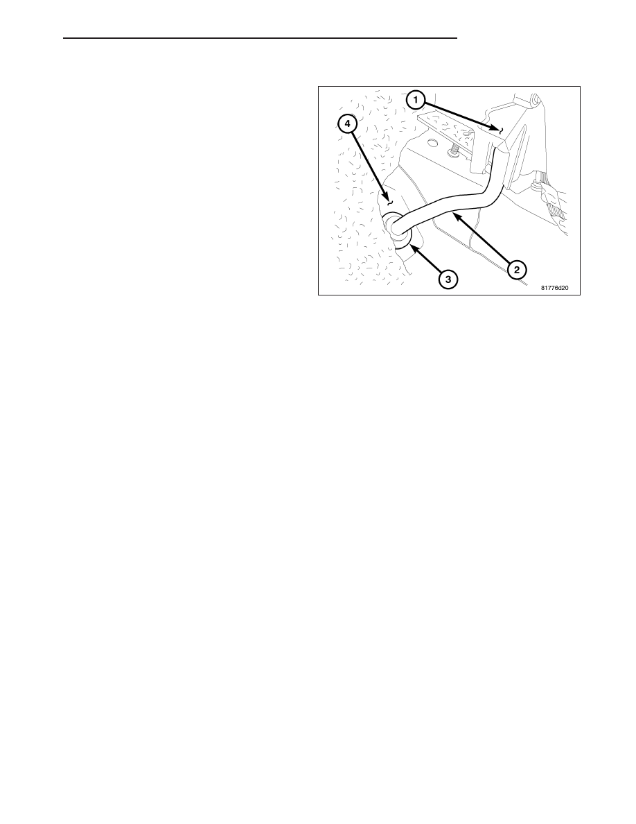
INSTALLATION
1. If removed, install the rubber grommet (3) onto the
driver side front floor panel (4). Make sure the
grommet is fully engaged to the floor panel.
2. Connect the condensation drain tube (2) onto the
drain port located on the bottom of the HVAC hous-
ing (1).
3. Install the condensation drain tube into the rubber
grommet.
4. Reinstall the floor carpet (refer to 23 - BODY/INTE-
RIOR/CARPETS
AND
FLOOR
MATS
-
INSTALLATION).
PM
PLUMBING
24 - 165